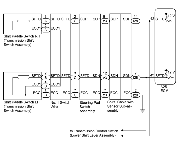
AUTOMATIC TRANSAXLE SYSTEM > Shift Paddle Switch Circuit |
| 1.READ VALUE USING INTELLIGENT TESTER (SPORT SHIFT SWITCH STATUS) |
Connect the intelligent tester to the DLC3.
Turn the ignition switch to ON.
Turn the intelligent tester on.
Enter the following menus: Powertrain / Engine and ECT / Data List.
Read the Data List according to the display on the intelligent tester.
| Tester Display | Measurement Item/Range | Normal Condition | Diagnostic Note |
| Sports Shift Up SW | Sport shift up switch status/ ON or OFF |
| - |
| Sports Shift Down SW | Sport shift down switch status/ ON or OFF |
| - |
| Result | Proceed to |
| Data List values are not normal | A |
| Data List values are normal | B |
|
| ||||
| A | |
 |
| 2.CHECK HARNESS AND CONNECTOR (SHIFT PADDLE SWITCH CIRCUIT) |
Disconnect the A25 ECM connector.
Measure the resistance according to the value(s) in the table below.
| Tester Connection | Condition | Specified Condition |
| A25-43 (SFTD) - Body ground | "-" (Down shift) shift paddle operated and held | Below 1 Ω |
| "-" (Down shift) shift paddle not operated | 10 kΩ or higher | |
| A25-42 (SFTU) - Body ground | "+" (Up shift) shift paddle operated and held | Below 1 Ω |
| "+" (Up shift) shift paddle not operated | 10 kΩ or higher |
|
| ||||
| OK | ||
 | ||
| ||
| 3.CHECK HARNESS AND CONNECTOR (SPIRAL CABLE WITH SENSOR SUB-ASSEMBLY - BODY GROUND) |
Disconnect the cable from the negative (-) battery terminal.
Wait for at least 90 seconds.
Remove the steering wheel assembly.
Remove the steering column cover.
Disconnect the I28 spiral cable with sensor sub-assembly connector.
Measure the resistance according to the value(s) in the table below.
| Tester Connection | Condition | Specified Condition |
| I28-2 (ECC) - Body ground | Always | Below 1 Ω |
|
| ||||
| OK | |
|
| 4.CHECK HARNESS AND CONNECTOR (SPIRAL CABLE WITH SENSOR SUB-ASSEMBLY - ECM) |
Disconnect the A25 ECM connector.
Measure the resistance according to the value(s) in the table below.
| Tester Connection | Condition | Specified Condition |
| A25-43 (SFTD) - I28-7 (SDN) | Always | Below 1 Ω |
| A25-43 (SFTD) or I28-7 (SDN) - Body ground | Always | 10 kΩ or higher |
| A25-42 (SFTU) - I28-14 (SUP) | Always | Below 1 Ω |
| A25-42 (SFTU) or I28-14 (SUP) - Body ground | Always | 10 kΩ or higher |
|
| ||||
| OK | |
|
| 5.CHECK HARNESS AND CONNECTOR (SPIRAL CABLE WITH SENSOR SUB-ASSEMBLY - SHIFT PADDLE SWITCH) |
Remove the horn button assembly.
Disconnect the z3 steering pad switch assembly connector.
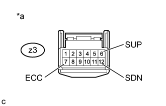 |
Measure the resistance according to the value(s) in the table below.
| *a | Component without harness connected (Steering Pad Switch Assembly) |
| Tester Connection | Condition | Specified Condition |
| z3-6 (SUP) - z3-7 (ECC) | "+" (Up shift) shift paddle operated and held | Below 1 Ω |
| "+" (Up shift) shift paddle not operated | 10 kΩ or higher | |
| z3-12 (SDN) - z3-7 (ECC) | "-" (Down shift) shift paddle operated and held | Below 1 Ω |
| "-" (Down shift) shift paddle not operated | 10 kΩ or higher |
|
| ||||
| OK | |
|
| 6.INSPECT SPIRAL CABLE WITH SENSOR SUB-ASSEMBLY |
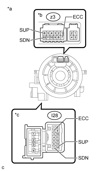 |
Disconnect the z3 steering pad switch connector.
| *a | Component without harness connected (Spiral Cable with Sensor Sub-assembly) |
| *b | Steering Pad Switch Assembly Side |
| *c | Vehicle Side |
Measure the resistance according to the value(s) in the table below.
| Tester Connection | Condition | Specified Condition |
| z3-7 (ECC) - I28-2 (ECC) | Always | Below 3 Ω |
| z3-6 (SUP) - I28-14 (SUP) | Always | Below 3 Ω |
| z3-12 (SDN) - I28-7 (SDN) | Always | Below 3 Ω |
| z3-7 (ECC) or I28-2 (ECC) - All other terminals | Always | 10 kΩ or higher |
| z3-6 (SUP) or I28-14 (SUP) - All other terminals | Always | 10 kΩ or higher |
| z3-12 (SDN) or I28-7 (SDN) - All other terminals | Always | 10 kΩ or higher |
| Result | Proceed to |
| OK | A |
| NG (for TMC, TMMR Made) | B |
| NG (for TMMK Made) | C |
|
| ||||
|
| ||||
| A | ||
| ||
| ||
| 7.INSPECT TRANSMISSION SHIFT SWITCH ASSEMBLY (SHIFT PADDLE SWITCH) |
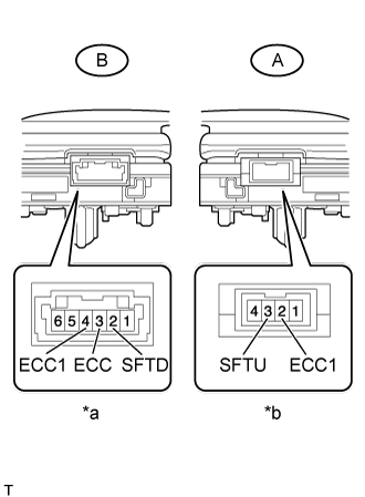 |
Disconnect the A and B transmission shift switch assembly connectors.
| *a | Component without harness connected (Shift Paddle Switch LH (Transmission Shift Switch Assembly)) |
| *b | Component without harness connected (Shift Paddle Switch RH (Transmission Shift Switch Assembly)) |
Measure the resistance according to the value(s) in the table below.
| Tester Connection | Condition | Specified Condition |
| B-3 (ECC) - B-2 (SFTD) | "-" (Down shift) shift paddle operated and held | Below 1 Ω |
| "-" (Down shift) shift paddle not operated | 10 kΩ or higher | |
| B-4 (ECC1) - B-2 (SFTD) | "-" (Down shift) shift paddle operated and held | Below 1 Ω |
| "-" (Down shift) shift paddle not operated | 10 kΩ or higher |
| Tester Connection | Condition | Specified Condition |
| A-3 (SFTU) - A-2 (ECC1) | "+" (Up shift) shift paddle operated and held | Below 1 Ω |
| "+" (Up shift) shift paddle not operated | 10 kΩ or higher |
|
| ||||
| OK | |
|
| 8.INSPECT NO. 1 SWITCH WIRE |
Connect the A and B transmission shift switch assembly connectors.
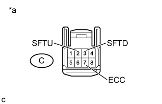 |
Disconnect the C No. 1 switch wire connector.
| *a | Front view of wire harness connector (to Steering Pad Switch Assembly) |
Measure the resistance according to the value(s) in the table below.
| Tester Connection | Condition | Specified Condition |
| C-3 (SFTD) - C-7 (ECC) | "-" (Down shift) shift paddle operated and held | Below 1 Ω |
| "-" (Down shift) shift paddle not operated | 10 kΩ or higher | |
| C-2 (SFTU) - C-7 (ECC) | "+" (Up shift) shift paddle operated and held | Below 1 Ω |
| "+" (Up shift) shift paddle not operated | 10 kΩ or higher |
|
| ||||
| OK | ||
| ||
| ||

