 |
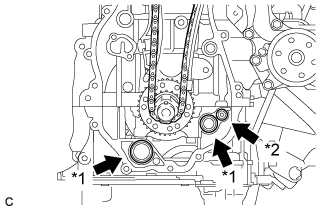
Apply a light coat of engine oil to 2 new oil pump gaskets and a new oil hole cover gasket.
| *1 | Oil Pump Gasket |
| *2 | Oil Hole Cover Gasket |
OIL PUMP > INSTALLATION |
| 1. INSTALL TIMING CHAIN COVER SUB-ASSEMBLY |
|
Apply a light coat of engine oil to 2 new oil pump gaskets and a new oil hole cover gasket.
| *1 | Oil Pump Gasket |
| *2 | Oil Hole Cover Gasket |
Install the 2 oil pump gaskets and oil hole cover gasket to the stiffening crankcase assembly.
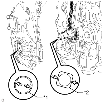 |
Align the drive rotor spline and the crankshaft timing sprocket as shown in the illustration.
| *1 | Drive Rotor Spline |
| *2 | Crankshaft Timing Sprocket |
Apply seal packing in a line to the timing chain cover sub-assembly as shown in the following illustration.
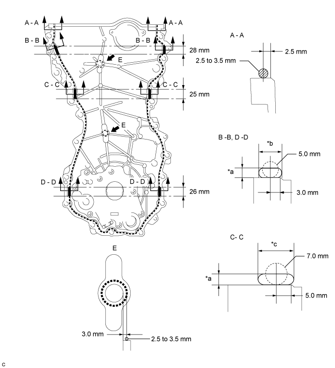
| *a | 3.0 mm or more | *b | 7.0 mm or more |
| *c | 13 mm or more | - | - |
| Area | Seal Packing Diameter (Round) | Distance from Edge of Cover to Center of Seal Packing | Seal Packing Application Length |
| Seal Packing Dimension (Flat) | |||
| Dashed Line | 2.5 to 3.5 mm (0.0984 to 0.138 in.) | 2.5 mm (0.0984 in.) | - |
| - | |||
| A - A | 2.5 to 3.5 mm (0.0984 to 0.138 in.) | 2.5 mm (0.0984 in.) | - |
| - | |||
| B - B | 5.0 mm (0.197 in.) | 3.0 mm (0.118 in.) | 28 mm (1.10 in.) |
| 7.0 mm (0.276 in.) or wider and 3.0 mm (0.118 in.) or thicker | |||
| C - C | 7.0 mm (0.276 in.) | 5.0 mm (0.197 in.) | 25 mm (0.984 in.) |
| 13 mm (0.512 in.) or wider and 3.0 mm (0.118 in.) or thicker | |||
| D - D | 5.0 mm (0.197 in.) | 3.0 mm (0.118 in.) | 26 mm (1.02 in.) |
| 7.0 mm (0.276 in.) or wider and 3.0 mm (0.118 in.) or thicker | |||
| E | 2.5 to 3.5 mm (0.0984 to 0.138 in.) | 3.0 mm (0.118 in.) | - |
| - |
Temporarily install the timing chain cover sub-assembly with the 17 bolts and 2 nuts.
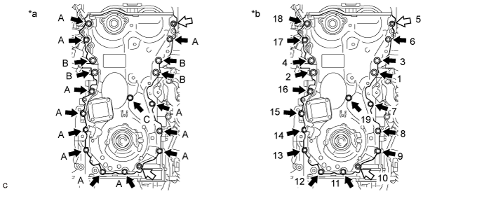
| *a | Torque | *b | Tightening Order |
 | Bolt |  | Nut |
| Item | Length | Thread Diameter |
| Bolt (A) | 30 mm (1.18 in.) | 8.0 mm (0.315 in.) |
| Bolt (B) | 35 mm (1.38 in.) | 10 mm (0.394 in.) |
| Bolt (C) | 45 mm (1.77 in.) | 8.0 mm (0.315 in.) |
Tighten the 17 bolts and 2 nuts in several steps, in the order shown in the illustration.
| 2. INSTALL ENGINE MOUNTING BRACKET RH |
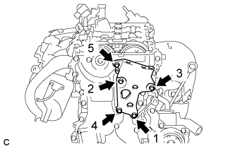 |
Install the engine mounting bracket RH with the 5 bolts in the order shown in the illustration.
| 3. INSTALL TIMING CHAIN COVER OIL SEAL |
Apply MP grease to the lip of a new timing chain cover oil seal.
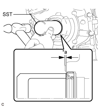 |
Using SST and a hammer, tap in the timing chain cover oil seal.
| *a | Standard Depth (from edge of the timing chain cover sub-assembly) |
| 4. INSTALL V-RIBBED BELT TENSIONER ASSEMBLY |
Install the V-ribbed belt tensioner assembly with the bolt.
Install the dust cover to the V-ribbed belt tensioner assembly.
| 5. INSTALL CAMSHAFT TIMING OIL CONTROL SOLENOID ASSEMBLY |
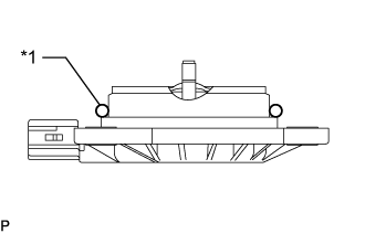 |
Apply engine oil to a new O-ring and install it to the camshaft timing oil control solenoid assembly as shown in the illustration.
| *1 | O-ring |
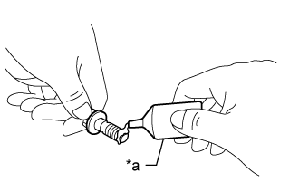 |
Apply adhesive to 2 or 3 threads of 2 new bolts.
| *a | Adhesive 1324 |
Install the camshaft timing oil control solenoid assembly to the timing chain cover sub-assembly with the 2 bolts.
Connect the camshaft timing oil control solenoid assembly connector.
| 6. INSTALL CRANKSHAFT PULLEY |
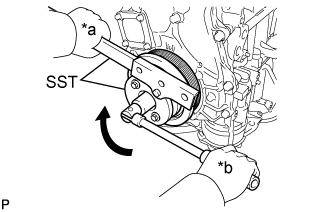 |
Align the crankshaft pulley key with the key groove of the crankshaft pulley.
| *a | Hold |
| *b | Turn |
Using SST, hold the crankshaft pulley and install the crankshaft pulley set bolt.
| 7. INSTALL CRANKSHAFT POSITION SENSOR |
Clean and degrease the threads of the bolt for the crankshaft position sensor.
Apply a light coat of engine oil to the O-ring of the crankshaft position sensor.
|
Apply adhesive to 2 or 3 threads of the bolt.
| *a | Adhesive 1324 |
Install the crankshaft position sensor to the timing chain cover sub-assembly with the bolt.
Connect the crankshaft position sensor connector.
| 8. INSTALL CYLINDER HEAD COVER SUB-ASSEMBLY |
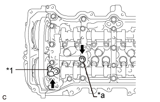 |
Apply a light coat of engine oil to a new camshaft bearing cap oil hole gasket and a new gasket.
| *1 | Camshaft Bearing Cap Oil Hole Gasket |
| *a | Gasket |
Install the camshaft bearing cap oil hole gasket to the No. 1 camshaft bearing cap.
Install the gasket to the No. 2 camshaft bearing cap.
Install a new cylinder head cover gasket to the cylinder head cover sub-assembly.
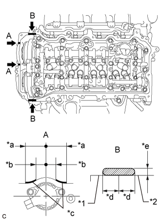 |
Apply seal packing as shown in the illustration.
| *1 | Timing Chain Cover Sub-assembly |
| *2 | Camshaft Housing Sub-assembly |
| *a | 45 mm (1.77 in.) |
| *b | 24 mm (0.945 in.) |
| *c | Seal Packing Diameter: 3.0 mm (0.118 in.) |
| *d | Application Width 5.0 mm (0.197 in.) |
| *e | Seal Packing Diameter: 3.0 to 6.0 mm (0.118 to 0.236 in.) |
| Seal Packing |
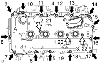 |
Align the cylinder head cover sub-assembly with the pin (A). Then align the cylinder head cover sub-assembly with the pin (B) and install the cylinder head cover sub-assembly.
| Bolt |
| Bolt with Seal Washer |
Install 3 new seal washers and the 17 bolts, and then tighten the bolts in the order shown in the illustration.
| 9. INSTALL EGR VALVE BRACKET |
Temporarily install the 2 EGR valve brackets with the 4 bolts.
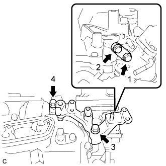 |
Tighten the 4 bolts in the order shown in the illustration.
Install the fuel hose bracket to the EGR valve bracket with the engine cover joint.
| 10. TEMPORARILY INSTALL FUEL PUMP WITH SEAL SUB-ASSEMBLY |
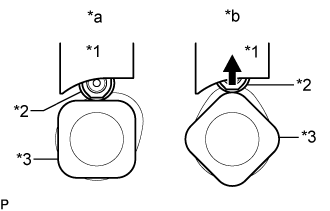 |
Turn the crankshaft pulley until the flat of the camshaft faces the fuel pump with seal sub- assembly installation hole of the cylinder head cover sub-assembly.
| *1 | Fuel Pump Lifter Guide |
| *2 | Fuel Pump Lifter Assembly |
| *3 | Camshaft |
| *a | Correct |
| *b | Incorrect |
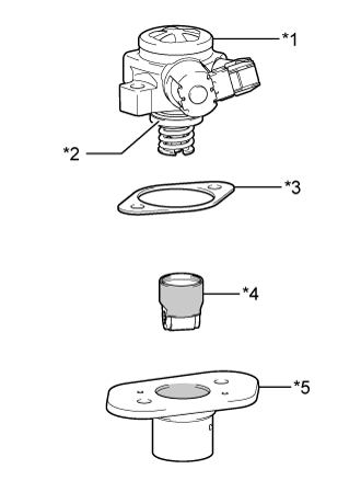 |
Apply engine oil to a new O-ring and install it to the fuel pump sub-assembly.
| *1 | Fuel Pump with Seal Sub-assembly |
| *2 | O-ring |
| *3 | Fuel Pump Insulator |
| *4 | Fuel Pump Lifter Assembly |
| *5 | Fuel Pump Lifter Guide |
 | Engine Oil Application Area |
Apply engine oil to the inside of the fuel pump lifter guide and the outside of the fuel pump lifter assembly.
Install the fuel pump lifter assembly to the fuel pump lifter guide.
Install the fuel pump insulator to the fuel pump lifter guide.
Install the fuel pump with seal sub-assembly to the fuel pump lifter guide.
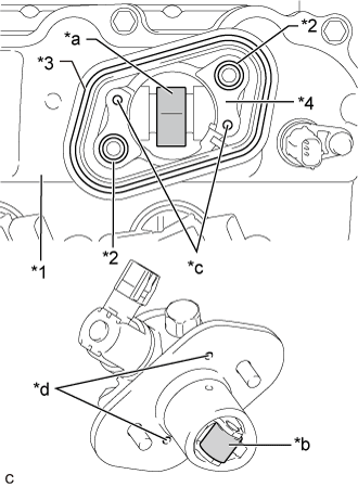 |
Apply 30 cc (1.8 cu. in.) of engine oil to the pump drive cam.
| *1 | Cylinder Head Cover Sub-assembly |
| *2 | O-ring |
| *3 | Fuel Pump Spacer Gasket |
| *4 | No. 4 Camshaft Bearing Cap |
| *a | Pump Drive Cam (Engine Oil Application Area) |
| *b | Pump Lifter (Engine Oil Application Area) |
| *c | Knock Pin |
| *d | Pin Hole |
Apply engine oil to the fuel pump lifter assembly.
Apply engine oil to 2 new O-rings and install them to the No. 4 camshaft bearing cap.
Install a new fuel pump spacer gasket to the cylinder head cover sub-assembly.
Set the fuel pump with seal sub-assembly on the cylinder head cover sub-assembly.
Temporarily install the fuel pump with seal sub-assembly with the 2 bolts, leaving some allowance for left and right movement.
| 11. TEMPORARILY INSTALL NO. 1 FUEL PIPE SUB-ASSEMBLY |
Connect the No. 1 fuel pipe sub-assembly to the fuel delivery pipe sub-assembly and tighten the union nut by hand.
Connect the No. 1 fuel pipe sub-assembly to the fuel pump with seal sub-assembly and tighten the union nut by hand.
| 12. INSTALL FUEL PUMP WITH SEAL SUB-ASSEMBLY |
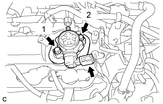 |
Tighten the 2 bolts in the order shown in the illustration.
Connect the fuel pump with seal sub-assembly connector.
| 13. INSTALL NO. 1 FUEL PIPE SUB-ASSEMBLY |
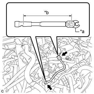 |
Using a 17 mm union nut wrench, tighten the union nuts on the fuel pump with seal sub-assembly side of the No. 1 fuel pipe sub-assembly.
| *a | 17 mm Union Nut Wrench |
| *b | Torque Wrench Fulcrum Length |
Using a 17 mm union nut wrench, tighten the union nuts on the fuel delivery pipe sub-assembly side of the No. 1 fuel pipe sub-assembly.
| 14. INSTALL NO. 1 FUEL PIPE |
Install the No. 1 fuel pipe and a new gasket to the fuel pump with seal sub-assembly.
| 15. CONNECT FUEL TUBE SUB-ASSEMBLY |
Connect the fuel tube sub-assembly to the No. 1 fuel pipe.
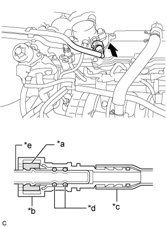 |
Align the fuel tube connector with the fuel pipe, and push them together until the fuel tube connector makes a "click" sound. If it is difficult to push the fuel pipe into the fuel tube connector, apply a small amount of clean engine oil to the tip of the fuel pipe and reinsert it.
| *a | Retainer |
| *b | Fuel Tube Connector |
| *c | Nylon Tube |
| *d | O-ring |
| *e | Fuel Pipe |
| Push |
After connecting the fuel pipes, check that the fuel pipe and fuel tube connector are securely connected by pulling on them.
Push in the fuel tube connector cover.
| 16. INSTALL FUEL PUMP PROTECTOR |
Install the fuel pump protector to the cylinder head cover sub-assembly with the 2 bolts.
| 17. CONNECT NO. 2 VENTILATION HOSE |
Connect the No. 2 ventilation hose to the PCV valve (ventilation valve sub-assembly) and slide the clip to secure it.
| 18. INSTALL IGNITION COIL ASSEMBLY |
Install the 4 ignition coil assemblies to the cylinder head cover sub-assembly with the 4 bolts.
Connect the 4 ignition coil assembly connectors.
| 19. REMOVE ENGINE ASSEMBLY FROM ENGINE STAND |