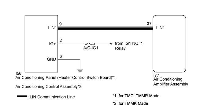
DTC B14B2 Lost Communication with Front Panel LIN |
| DTC No. | DTC Detection Condition | Trouble Area |
| B14B2 | for TMC, TMMR Made
for TMMK Made
| for TMC, TMMR Made
for TMMK Made
|
| 1.CONFIRM MODEL |
| Result | Proceed to |
| for TMC, TMMR Made | A |
| for TMMK Made | B |
|
| ||||
| A | |
 |
| 2.CHECK HARNESS AND CONNECTOR (AIR CONDITIONING PANEL (HEATER CONTROL SWITCH BOARD) - IG CIRCUIT) |
Disconnect the I56 air conditioning panel (heater control switch board) connector.
Measure the voltage according to the value(s) in the table below.
| Tester Connection | Condition | Specified Condition |
| I56-2 (IG+) - Body ground | Ignition switch off | Below 1 V |
| I56-2 (IG+) - Body ground | Ignition switch ON | 11 to 14 V |
|
| ||||
| OK | |
|
| 3.CHECK HARNESS AND CONNECTOR (AIR CONDITIONING PANEL (HEATER CONTROL SWITCH BOARD) - BODY GROUND) |
Measure the resistance according to the value(s) in the table below.
| Tester Connection | Condition | Specified Condition |
| I56-6 (GND) - Body ground | Always | Below 1 Ω |
|
| ||||
| OK | |
|
| 4.CHECK HARNESS AND CONNECTOR (AIR CONDITIONING AMPLIFIER ASSEMBLY - AIR CONDITIONING PANEL (HEATER CONTROL SWITCH BOARD)) |
Disconnect the I77 air conditioning amplifier assembly connector.
Measure the resistance according to the value(s) in the table below.
| Tester Connection | Condition | Specified Condition |
| I56-9 (LIN1) - I77-37 (LIN1) | Always | Below 1 Ω |
| I56-9 (LIN1) - Body ground | Always | 10 kΩ or higher |
|
| ||||
| OK | |
|
| 5.REPLACE AIR CONDITIONING PANEL (HEATER CONTROL SWITCH BOARD) |
Replace the air conditioning panel (heater control switch board) (Click here).
| Result | Proceed to |
| OK | A |
| NG (When troubleshooting according to Problem Symptoms Table) | B |
| NG (When troubleshooting according to the DTC) | C |
|
| ||||
|
| ||||
| A | ||
 | ||
| ||
| 6.CHECK HARNESS AND CONNECTOR (AIR CONDITIONING CONTROL ASSEMBLY - IG CIRCUIT) |
Disconnect the I56 air conditioning control assembly connector.
Measure the voltage according to the value(s) in the table below.
| Tester Connection | Condition | Specified Condition |
| I56-2 (IG+) - Body ground | Ignition switch off | Below 1 V |
| I56-2 (IG+) - Body ground | Ignition switch ON | 11 to 14 V |
|
| ||||
| OK | |
|
| 7.CHECK HARNESS AND CONNECTOR (AIR CONDITIONING CONTROL ASSEMBLY - BODY GROUND) |
Measure the resistance according to the value(s) in the table below.
| Tester Connection | Condition | Specified Condition |
| I56-6 (GND) - Body ground | Always | Below 1 Ω |
|
| ||||
| OK | |
|
| 8.CHECK HARNESS AND CONNECTOR (AIR CONDITIONING AMPLIFIER ASSEMBLY - AIR CONDITIONING CONTROL ASSEMBLY) |
Disconnect the I77 air conditioning amplifier assembly connector.
Measure the resistance according to the value(s) in the table below.
| Tester Connection | Condition | Specified Condition |
| I56-9 (LIN1) - I77-37 (LIN1) | Always | Below 1 Ω |
| I56-9 (LIN1) - Body ground | Always | 10 kΩ or higher |
|
| ||||
| OK | |
|
| 9.REPLACE AIR CONDITIONING CONTROL ASSEMBLY |
Replace the air conditioning control assembly (Click here).
| Result | Proceed to |
| OK | A |
| NG (When troubleshooting according to Problem Symptoms Table) | B |
| NG (When troubleshooting according to the DTC) | C |
|
| ||||
|
| ||||
| A | ||
| ||
| ||

