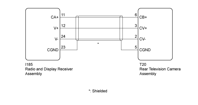
PARKING ASSIST MONITOR SYSTEM > Image from Camera for Parking Assist Monitor is Abnormal |
| 1.CHECK HARNESS AND CONNECTOR (RADIO AND DISPLAY RECEIVER ASSEMBLY - REAR TELEVISION CAMERA ASSEMBLY) |
Disconnect the I185 radio and display receiver assembly connector.
Disconnect the T20 rear television camera assembly connector.
Measure the resistance according to the value(s) in the table below.
| Tester Connection | Condition | Specified Condition |
| I185-11 (CA+) - T20-6 (CB+) | Always | Below 1 Ω |
| I185-12 (V+) - T20-3 (CV+) | Always | Below 1 Ω |
| I185-24 (V-) - T20-2 (CV-) | Always | Below 1 Ω |
| I185-23 (CGND) - T20-5 (CGND) | Always | Below 1 Ω |
| I185-11 (CA+) - Body ground | Always | 10 kΩ or higher |
| I185-12 (V+) - Body ground | Always | 10 kΩ or higher |
| I185-24 (V-) - Body ground | Always | 10 kΩ or higher |
| I185-23 (CGND) - Body ground | Always | 10 kΩ or higher |
|
| ||||
| OK | |
 |
| 2.REPLACE REAR TELEVISION CAMERA ASSEMBLY |
Replace the rear television camera assembly with a new or known good one (Click here).
Check that the parking assist monitor system operates normally.
|
| ||||
| OK | ||
 | ||
| ||
