Home › Brake › BRAKE SYSTEM (OTHER) › VACUUM WARNING SWITCH

VACUUM WARNING SWITCH > ON-VEHICLE INSPECTION

for Preparation Click here


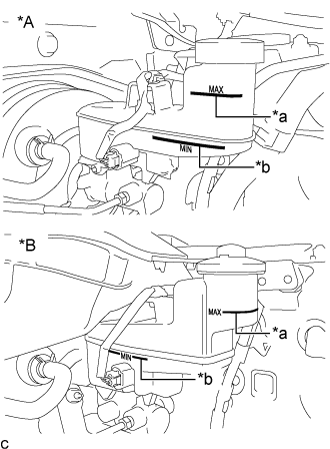
1. INSPECT BRAKE FLUID LEVEL IN RESERVOIR


    C321681E01
  1. Check the fluid level.
    Text in Illustration 
    *A
    for TMC, TMMR Made
    *B
    for TMMK Made
    *a
    MAX Line
    *b
    MIN Line
    If brake fluid level is lower than the MIN line, check for leaks and inspect the disc brake pads. If necessary, refill the reservoir with brake fluid to the MAX line after repair or replacement.

    Brake Fluid:
    SAE J1703 or FMVSS No. 116 DOT 3

    NOTICE:
    If using a dropper to adjust the fluid amount, make sure that the dropper has not been used with mineral oils, water or deteriorated brake fluid. Sealed areas may deteriorate and lead to fluid leaks, or the fluid may deteriorate and lead to decreased efficiency.
2. INSPECT BRAKE BOOSTER ASSEMBLY
(Click here)


3. REMOVE WINDSHIELD WIPER MOTOR AND LINK ASSEMBLY
(Click here)


4. REMOVE FRONT OUTER COWL TOP PANEL SUB-ASSEMBLY


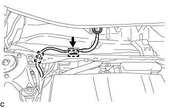
  1. w/ Windshield Deicer System:


      C309273
    1. Disengage the 2 clamps.

    2. Disconnect the connector and separate the wire harness from the front outer cowl top panel sub-assembly.


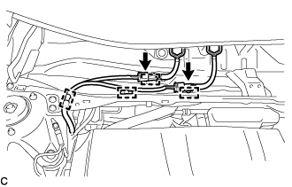
  1. w/ Heated Windshield Defroster System:


      C309274
    1. Disengage the 4 clamps.

    2. Disconnect the 2 connectors and separate the wire harness from the front outer cowl top panel sub-assembly.


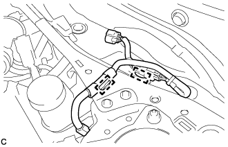
    C239198
  1. Disengage the 2 clamps and separate the wire harness from the front outer cowl top panel sub-assembly.


    C239185
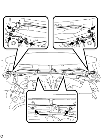
  1. Remove the 10 bolts and front outer cowl top panel sub-assembly.


5. INSPECT VACUUM WARNING SWITCH ASSEMBLY
  1. Start the engine and stop it after 1 or 2 minutes.

  1. Disconnect the connector from the vacuum warning switch assembly.

  1. Measure the resistance of the vacuum warning switch assembly.

    Standard Resistance:
    10 kΩ or higher

  1. With the engine stopped, depress the brake pedal several times to release vacuum from the brake booster assembly, and measure the resistance of the vacuum warning switch assembly.

    Standard Resistance:
    Below 1 Ω

  1. Connect the connector to the vacuum warning switch assembly.


6. INSTALL FRONT OUTER COWL TOP PANEL SUB-ASSEMBLY
  1. Install the front outer cowl top panel sub-assembly with the 10 bolts.

    Torque:
    10 N*m{ 102 kgf*cm , 7 ft.*lbf }

  1. Engage the 2 clamps to install the wire harness to the front outer cowl top panel sub-assembly.

  1. w/ Windshield Deicer System:

    1. Connect the connector.

    2. Engage the 2 clamps to install the wire harness to the front outer cowl top panel sub-assembly.

  1. w/ Heated Windshield Defroster System:

    1. Connect the 2 connectors.

    2. Engage the 4 clamps to install the wire harness to the front outer cowl top panel sub-assembly.


7. INSTALL WINDSHIELD WIPER MOTOR AND LINK ASSEMBLY