 |
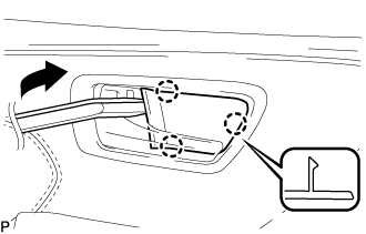
Using a moulding remover, disengage the 3 claws to remove the front door inside handle bezel plug as shown in the illustration.
FRONT DOOR LOCK (for TMMK Made) > REMOVAL |
| 1. PRECAUTION |
| 2. DISCONNECT CABLE FROM NEGATIVE BATTERY TERMINAL |
| 3. REMOVE FRONT DOOR INSIDE HANDLE BEZEL PLUG |
|
Using a moulding remover, disengage the 3 claws to remove the front door inside handle bezel plug as shown in the illustration.
| 4. REMOVE FRONT DOOR FRONT LOWER FRAME UPPER COVER |
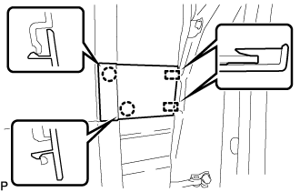 |
Disengage the 2 claws and 2 guides to remove the front door front lower frame upper cover.
| 5. REMOVE POWER WINDOW REGULATOR MASTER SWITCH ASSEMBLY WITH FRONT DOOR ARMREST BASE PANEL (for Driver Side) |
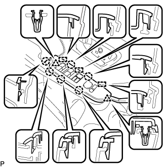 |
Using a moulding remover, disengage the 2 clips, 6 claws and 3 guides.
Disconnect each connector to remove the power window regulator master switch assembly with front door armrest base panel.
| 6. REMOVE POWER WINDOW REGULATOR SWITCH ASSEMBLY WITH FRONT DOOR ARMREST BASE PANEL (for Front Passenger Side) |
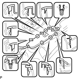 |
Using a moulding remover, disengage the 2 clips, 6 claws and 3 guides.
Disconnect each connector to remove the power window regulator switch assembly with front door armrest base panel.
| 7. REMOVE FRONT ARMREST ASSEMBLY |
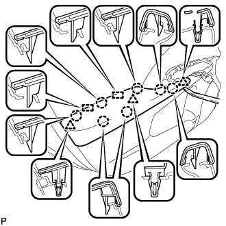 |
Using a moulding remover, disengage the 3 clips, 7 claws and 2 guides to remove the front armrest assembly.
| 8. REMOVE COURTESY LIGHT ASSEMBLY |
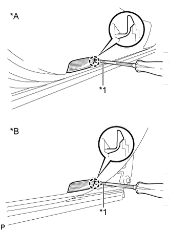 |
Using a screwdriver with its tip wrapped with protective tape, disengage the claw.
| *A | for LH Side |
| *B | for RH Side |
| *1 | Protective Tape |
Disconnect the connector and remove the courtesy light assembly.
| 9. REMOVE FRONT DOOR TRIM BOARD SUB-ASSEMBLY |
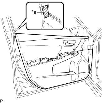 |
Apply protective tape to the front door panel.
| *a | Protective Tape |
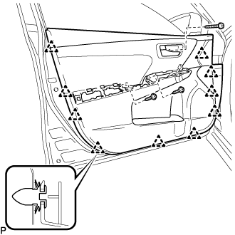 |
Remove the 3 screws.
Using a clip remover, disengage the 10 clips.
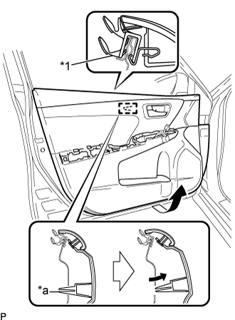 |
Pull out the front door trim board sub-assembly as shown in the illustration.
| *1 | Front Door Inner Glass Weatherstrip |
| *a | Reference Boss |
Disengage the reference boss from the front door panel.
Raise the front door trim board sub-assembly to remove the front door trim board sub-assembly together with the front door inner glass weatherstrip.
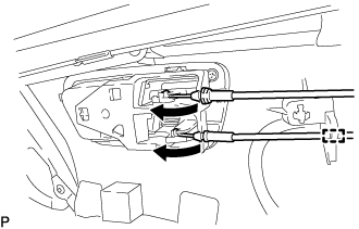 |
Disengage the clamp.
Disconnect the front door lock remote control cable assembly and front door inside locking cable assembly as shown in the illustration.
| 10. REMOVE FRONT DOOR INNER GLASS WEATHERSTRIP |
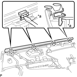 |
Using a screwdriver, disengage the 4 claws and remove the front door inner glass weatherstrip from the front door trim board sub-assembly as shown in the illustration.
| *a | Screwdriver |
| 11. REMOVE DOOR SIDE AIRBAG SENSOR |
Check that the engine switch is off.
Check that the cable is disconnected from the negative (-) battery terminal.
Disconnect the connector from the door side airbag sensor.
Push down the white housing lock and slide the yellow CPA. (At this time, the connector cannot be disconnected yet.)
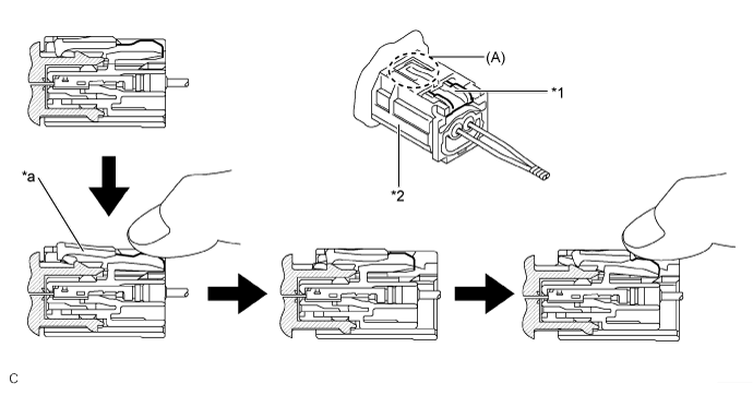
| *1 | White Housing Lock | *2 | Yellow CPA |
| *a | Connector Lock is Released | - | - |
Push down the white housing lock again and disconnect the connector.
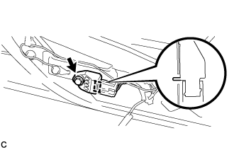 |
Remove the bolt and door side airbag sensor from the front door panel.
After disconnecting the connector, check that the position of the white housing lock is correct as shown in the illustration.
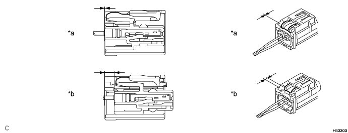
| *a | Incorrect | *b | Correct |
| 12. REMOVE FRONT DOOR SERVICE HOLE COVER |
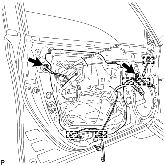 |
Remove the bolt.
Disconnect each connector.
Disengage the 5 clamps.
Pass the front door lock remote control cable assembly, front door inside locking cable assembly and each connector through the front door service hole cover.
Remove the front door service hole cover.
| 13. REMOVE NO. 1 FRONT DOOR SERVICE HOLE SEAL |
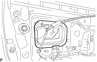 |
Remove the No. 1 front door service hole seal.
| 14. REMOVE NO. 2 FRONT DOOR SERVICE HOLE SEAL |
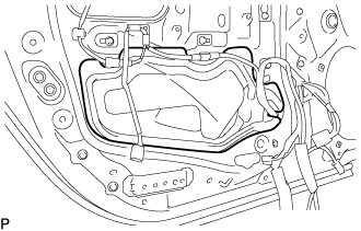 |
Remove the No. 2 front door service hole seal.
| 15. REMOVE FRONT DOOR GLASS SUB-ASSEMBLY |
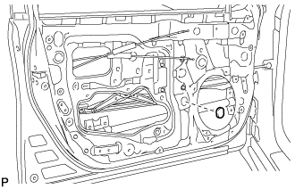 |
Remove the grommet.
Connect the cable to the negative (-) battery terminal.
for Driver Side:
Connect the power window regulator master switch assembly and move the front door glass sub-assembly so that the door glass bolts can be seen.
Disconnect the power window regulator master switch assembly.
for Front Passenger Side:
Connect the power window regulator switch assembly and move the front door glass sub-assembly so that the door glass bolts can be seen.
Disconnect the power window regulator switch assembly.
Disconnect the cable from the negative (-) battery terminal.
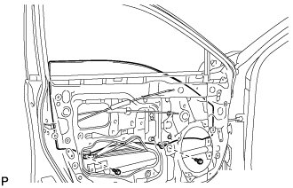 |
Remove the 2 bolts.
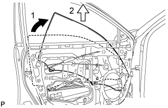 |
Remove the front door glass sub-assembly as indicated by the arrows, in the order shown in the illustration.
| 16. REMOVE FRONT DOOR GLASS RUN |
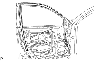 |
Remove the front door glass run.
| 17. REMOVE FRONT DOOR REAR LOWER FRAME SUB-ASSEMBLY |
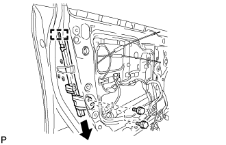 |
Remove the 2 bolts.
Disengage the guide and remove the front door rear lower frame sub-assembly as shown in the illustration.
| 18. REMOVE FRONT DOOR OUTSIDE HANDLE COVER WITH LOCK CYLINDER ASSEMBLY (w/ Lock Cylinder) |
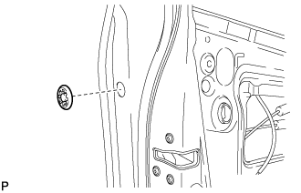 |
Remove the hole plug.
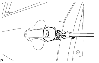 |
Using a T30 "TORX" socket wrench, loosen the screw and remove the front door outside handle cover with lock cylinder assembly.
| 19. REMOVE FRONT DOOR LOCK WITH MOTOR ASSEMBLY |
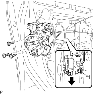 |
Using a T30 "TORX" socket wrench, remove the 3 screws.
| *1 | Front Door Lock Open Rod |
Slide the front door lock with motor assembly downward to disconnect the front door lock open rod and remove the front door lock with motor assembly and cables as a unit.
When reusing the front door lock with motor assembly:
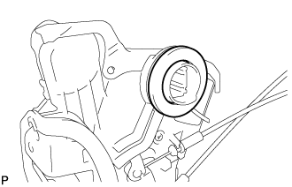 |
Remove the door lock wiring harness seal from the front door lock with motor assembly.
| 20. REMOVE FRONT DOOR LOCK REMOTE CONTROL CABLE ASSEMBLY |
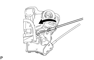 |
Remove the front door lock remote control cable assembly as shown in the illustration.
| 21. REMOVE FRONT DOOR INSIDE LOCKING CABLE ASSEMBLY |
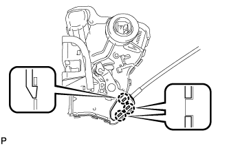 |
Using a screwdriver, disengage the 3 claws.
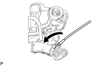 |
Remove the front door inside locking cable assembly as shown in the illustration.