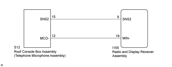
DTC B1579 Voice Recognition Microphone Disconnected |
| DTC No. | DTC Detection Condition | Trouble Area |
| B1579 | Microphone signal is lost. |
|
| 1.INSPECT RADIO AND DISPLAY RECEIVER ASSEMBLY |
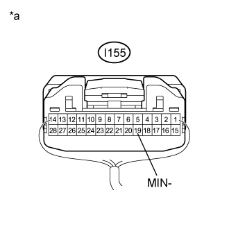 |
Measure the resistance according to the value(s) in the table below.
| Tester Connection | Condition | Specified Condition |
| I155-19 (MIN-) - Body ground | Always | Below 1 Ω |
| *a | Component with harness connected (Radio and Display Receiver Assembly) |
|
| ||||
| OK | |
 |
| 2.CHECK HARNESS AND CONNECTOR (RADIO AND DISPLAY RECEIVER ASSEMBLY - ROOF CONSOLE BOX ASSEMBLY (TELEPHONE MICROPHONE ASSEMBLY)) |
Disconnect the I155 radio and display receiver assembly connector.
Disconnect the S12 roof console box assembly (telephone microphone assembly) connector.
Measure the resistance according to the value(s) in the table below.
| Tester Connection | Condition | Specified Condition |
| I155-6 (SNS2) - S12-15 (SNS2) | Always | Below 1 Ω |
| I155-19 (MIN-) - S12-12 (MCO-) | Always | Below 1 Ω |
| I155-6 (SNS2) - Body ground | Always | 10 kΩ or higher |
| I155-19 (MIN-) - Body ground | Always | 10 kΩ or higher |
|
| ||||
| OK | |
|
| 3.INSPECT ROOF CONSOLE BOX ASSEMBLY (TELEPHONE MICROPHONE ASSEMBLY) |
Remove the roof console box assembly (telephone microphone assembly) (Click here).
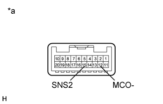 |
Measure the resistance according to the value(s) in the table below.
| Tester Connection | Condition | Specified Condition |
| 15 (SNS2) - 12 (MCO-) | Always | Below 1 Ω |
| *a | Component without harness connected (Roof Console Box Assembly (Telephone Microphone Assembly)) |
|
| ||||
| OK | ||
 | ||
| ||
