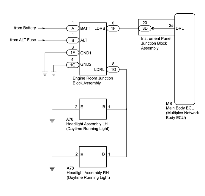
LIGHTING SYSTEM > Daytime Running Light Relay Circuit |
| for TMC, TMMR Made: |
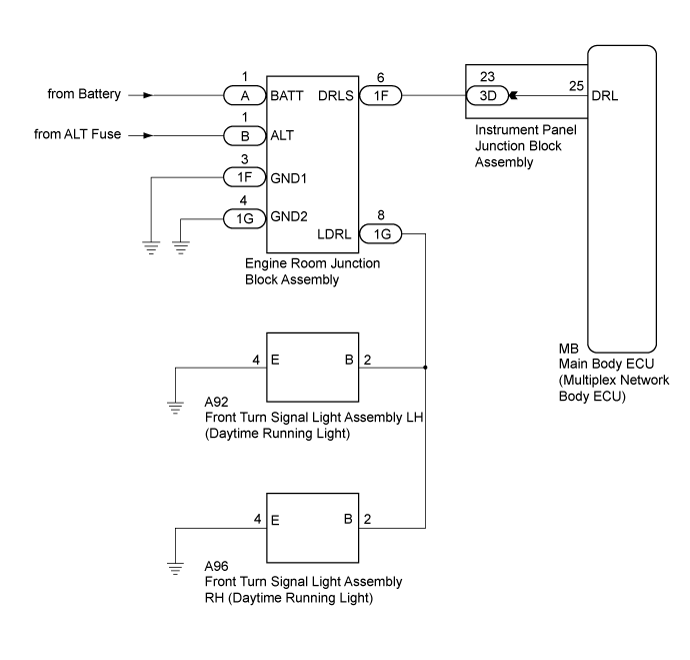
| for TMMK Made: |
| 1.CONFIRM MODEL |
| Result | Proceed to |
| for TMC, TMMR Made | A |
| for TMMK Made | B |
|
| ||||
| A | |
 |
| 2.CHECK OPERATION (CLEARANCE LIGHTS) |
Check the operation of the clearance lights.
|
| ||||
| OK | |
|
| 3.PERFORM ACTIVE TEST USING INTELLIGENT TESTER |
Connect the intelligent tester to the DLC3.
Turn the ignition switch to ON.
Turn the intelligent tester on.
Enter the following menus: Body / Main Body / Active Test.
Perform the Active Test according to the display on the intelligent tester.
| Tester Display | Test Part | Control Range | Diagnostic Note |
| Daytime Running Light | Daytime running lights | ON/OFF | - |
|
| ||||
| OK | ||
 | ||
| ||
| 4.CHECK ENGINE ROOM JUNCTION BLOCK ASSEMBLY |
Using a voltmeter, check the signal reading of the engine room junction block assembly .
|
| ||||
| OK | |
|
| 5.CHECK HARNESS AND CONNECTOR (ENGINE ROOM JUNCTION BLOCK ASSEMBLY POWER SOURCE AND BODY GROUND) |
Remove the engine room junction block assembly from the engine room relay block and junction block assembly (Click here).
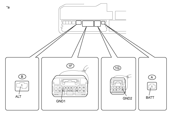
| *a | Component without engine room junction block assembly (Engine Room Relay Block and Junction Block Assembly) | - | - |
Measure the voltage according to the value(s) in the table below.
| Tester Connection | Condition | Specified Condition |
| A-1 (BATT) - Body ground | Always | 11 to 14 V |
| B-1 (ALT) - Body ground | Always | 11 to 14 V |
Measure the resistance according to the value(s) in the table below.
| Tester Connection | Condition | Specified Condition |
| 1F-3 (GND1) - Body ground | Always | Below 1 Ω |
| 1G-4 (GND2) - Body ground | Always | Below 1 Ω |
|
| ||||
| OK | |
|
| 6.CHECK HARNESS AND CONNECTOR (ENGINE ROOM JUNCTION BLOCK ASSEMBLY - INSTRUMENT PANEL JUNCTION BLOCK ASSEMBLY) |
Disconnect the 3D main body ECU (multiplex network body ECU) connector.
for TMC, TMMR Made:
Measure the resistance according to the value(s) in the table below.
| Tester Connection | Condition | Specified Condition |
| 1F-6 (LDRS) - 3D-23 | Always | Below 1 Ω |
| 3D-23 - Body ground | Always | 10 kΩ or higher |
for TMMK Made:
Measure the resistance according to the value(s) in the table below.
| Tester Connection | Condition | Specified Condition |
| 1F-6 (DRLS) - 3D-23 | Always | Below 1 Ω |
| 3D-23 - Body ground | Always | 10 kΩ or higher |
|
| ||||
| OK | |
|
| 7.INSPECT INSTRUMENT PANEL JUNCTION BLOCK ASSEMBLY |
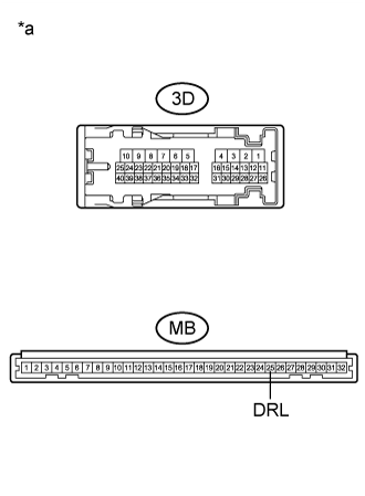 |
Remove the instrument panel junction block assembly (Click here).
Remove the main body ECU (multiplex network body ECU) from the instrument panel junction block assembly.
Measure the resistance according to the value(s) in the table below.
| Tester Connection | Condition | Specified Condition |
| 3D-23 - MB-25 (DRL) | Always | Below 1 Ω |
| *a | Component without harness connected (Instrument Panel Junction Block Assembly) |
|
| ||||
| OK | |
|
| 8.CHECK HARNESS AND CONNECTOR (ENGINE ROOM JUNCTION BLOCK ASSEMBLY - HEADLIGHT ASSEMBLY OR FRONT TURN SIGNAL LIGHT ASSEMBLY) |
for TMC, TMMR Made:
Disconnect the A76 headlight assembly LH connector.
Disconnect the A78 headlight assembly RH connector.
Measure the resistance according to the value(s) in the table below.
| Tester Connection | Condition | Specified Condition |
| 1G-8 (LDRL) - A76-1 (B) | Always | Below 1 Ω |
| 1G-8 (LDRL) - A78-1 (B) | Always | Below 1 Ω |
| 1G-8 (LDRL) - Body ground | Always | 10 kΩ or higher |
for TMMK Made:
Disconnect the A92 front turn signal light assembly LH connector.
Disconnect the A96 front turn signal light assembly RH connector.
Measure the resistance according to the value(s) in the table below.
| Tester Connection | Condition | Specified Condition |
| 1G-8 (LDRL) - A92-2 (B) | Always | Below 1 Ω |
| 1G-8 (LDRL) - A96-2 (B) | Always | Below 1 Ω |
| 1G-8 (LDRL) - Body ground | Always | 10 kΩ or higher |
|
| ||||
| OK | |
|
| 9.REPLACE ENGINE ROOM JUNCTION BLOCK ASSEMBLY |
Replace the engine room junction block assembly with a new or known good one (Click here).
Check that the daytime running lights operate normally.
|
| ||||
| OK | ||
| ||
| ||

