 |
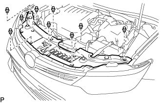
Remove the 9 clips and cool air intake duct seal.
CAMSHAFT > REMOVAL |
| 1. PRECAUTION |
| 2. DISCONNECT CABLE FROM NEGATIVE BATTERY TERMINAL |
| 3. REMOVE FRONT WHEEL RH |
| 4. REMOVE FRONT WHEEL OPENING EXTENSION PAD RH |
Remove the 3 screws and front wheel opening extension pad RH.
| 5. REMOVE ENGINE UNDER COVER RH |
Remove the 3 screws, 3 clips and engine under cover RH.
| 6. REMOVE FRONT FENDER APRON SEAL RH |
Remove the 2 bolts, clip and front fender apron seal RH.
| 7. REMOVE COOL AIR INTAKE DUCT SEAL |
|
Remove the 9 clips and cool air intake duct seal.
| 8. REMOVE NO. 1 ENGINE COVER SUB-ASSEMBLY |
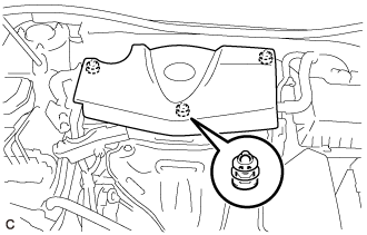 |
Disengage the 3 grommets to remove the No. 1 engine cover sub-assembly.
| 9. REMOVE INLET AIR CLEANER ASSEMBLY |
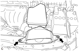 |
Remove the 2 bolts and inlet air cleaner assembly.
| 10. REMOVE AIR CLEANER CAP WITH AIR CLEANER HOSE |
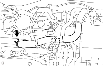 |
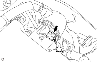
Slide the clip and disconnect the ventilation hose from the cylinder head cover sub-assembly.
Disengage the ventilation hose clamp.
 |
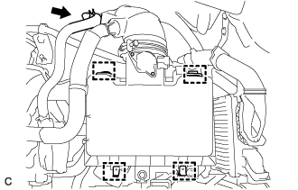
Disconnect the mass air flow meter sub-assembly connector.
Disengage the wire harness clamp.
 |
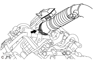
Disconnect the union to connector tube hose from the air cleaner hose sub-assembly.
Disengage the 2 air cleaner cap clamps and 2 guides.
 |
Loosen the hose clamp and remove the air cleaner cap with air cleaner hose from the throttle body with motor assembly.
| 11. REMOVE AIR CLEANER FILTER ELEMENT SUB-ASSEMBLY |
Remove the air cleaner filter element sub-assembly from the air cleaner case sub-assembly.
| 12. REMOVE AIR CLEANER CASE SUB-ASSEMBLY |
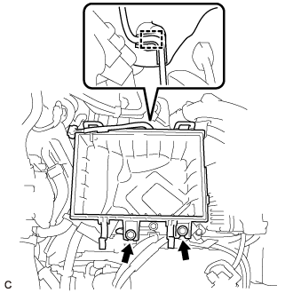 |
Disconnect the wire harness clamp.
Remove the 2 bolts and air cleaner case sub-assembly.
| 13. DISCONNECT ENGINE WIRE |
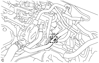 |
Disengage the clamp to separate the heater inlet water hose.
Disconnect the 18 connectors and 8 clamps.
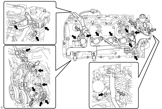
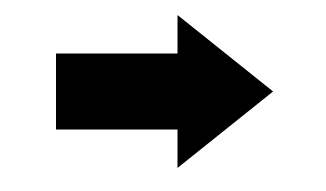 | Connector |  | Nut |
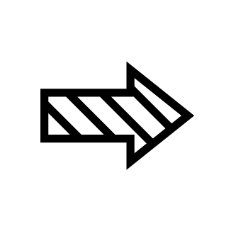 | Bolt | - | - |
Remove the 4 nuts and 5 bolts and disconnect the engine wire from the engine assembly.
| 14. REMOVE FUEL PUMP WITH SEAL SUB-ASSEMBLY (for High Pressure) |
| 15. REMOVE VACUUM PUMP ASSEMBLY |
| 16. REMOVE EARTH WIRE |
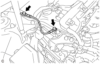 |
Remove the 2 bolts and earth wire.
| 17. REMOVE NO. 2 ENGINE MOUNTING STAY RH |
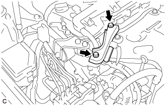 |
Remove the 2 bolts and No. 2 engine mounting stay RH.
| 18. REMOVE ENGINE MOVING CONTROL ROD BRACKET |
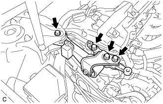 |
Remove the 4 bolts and engine moving control rod bracket.
| 19. REMOVE IGNITION COIL ASSEMBLY |
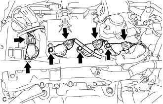 |
Disconnect the 4 ignition coil assembly connectors.
Remove the 4 bolts and 4 ignition coil assemblies from the cylinder head cover sub-assembly.
| 20. DISCONNECT NO. 2 VENTILATION HOSE |
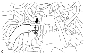 |
Slide the clip and disconnect the No. 2 ventilation hose from the PCV valve (ventilation valve sub-assembly).
| 21. REMOVE CYLINDER HEAD COVER SUB-ASSEMBLY |
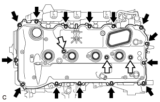 |
Remove the 17 bolts, 3 seal washers, cylinder head cover sub-assembly and cylinder head cover gasket.
| Bolt |
| Bolt with Seal Washer |
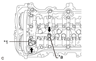 |
Remove the camshaft bearing cap oil hole gasket from the No. 1 camshaft bearing cap.
| *1 | Camshaft Bearing Cap Oil Hole Gasket |
| *a | Gasket |
Remove the gasket from the No. 2 camshaft bearing cap.
| 22. SET NO. 1 CYLINDER TO TDC/COMPRESSION |
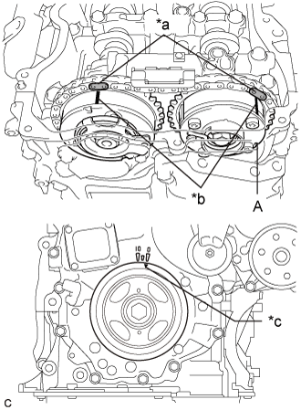 |
Turn the crankshaft pulley until its timing notch (groove) and the timing mark "0" of the timing chain cover sub-assembly are aligned.
| *a | Paint Mark |
| *b | Timing Mark |
| *c | Timing Notch (Groove) |
Check that both timing marks on the camshaft timing gear assembly and camshaft timing exhaust gear assembly are facing upward as shown in the illustration. If not, turn the crankshaft 1 revolution (360°) to align the timing marks as shown in the illustration.
Place paint marks on the chain sub-assembly in alignment with the timing marks on the camshaft timing gear assembly and camshaft timing exhaust gear assembly.
| 23. REMOVE TIMING CHAIN COVER PLATE |
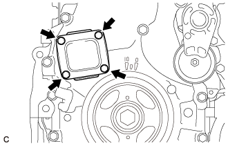 |
Remove the 4 bolts, timing chain cover plate and gasket.
| 24. REMOVE NO. 1 CHAIN TENSIONER ASSEMBLY |
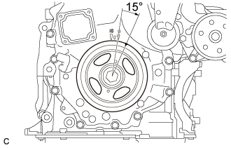 |
Turn the crankshaft pulley approximately 15° clockwise.
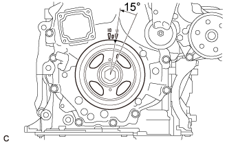 |
Turn the crankshaft pulley approximately 15° counterclockwise.
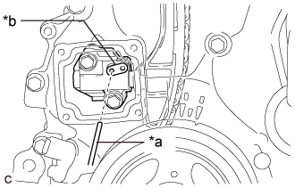 |
Align the holes of the stopper plate and No. 1 chain tensioner assembly, and insert a pin into the stopper plate hole to lock the No. 1 chain tensioner assembly.
| *a | Pin |
| *b | Stopper Plate |
|
Turn the crankshaft pulley approximately 15° clockwise.
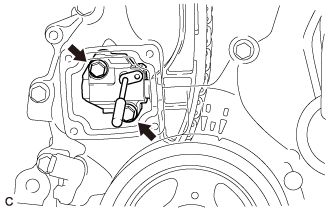 |
Remove the 2 bolts, No. 1 chain tensioner assembly and gasket.
|
Turn the crankshaft pulley approximately 15° counterclockwise.
| 25. REMOVE TIMING CHAIN GUIDE |
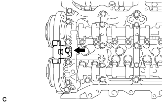 |
Remove the bolt and timing chain guide.
| 26. REMOVE CAMSHAFT TIMING OIL CONTROL SOLENOID ASSEMBLY |
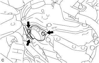 |
Disconnect the camshaft timing oil control solenoid assembly connector.
Remove the 2 bolts and camshaft timing oil control solenoid assembly from the timing chain cover sub-assembly.
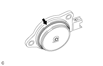 |
Remove the O-ring from the camshaft timing oil control solenoid assembly.
| 27. REMOVE CAMSHAFT TIMING GEAR BOLT |
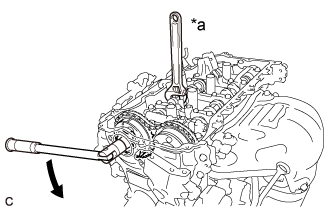 |
Hold the hexagonal portion of the camshaft with a wrench and remove the camshaft timing gear bolt from the camshaft.
| *a | Hold |
| Turn |
| 28. REMOVE CAMSHAFT BEARING CAP |
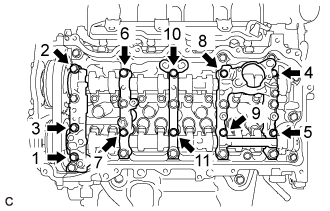 |
Remove the 11 bolts in several steps in the order shown in the illustration.
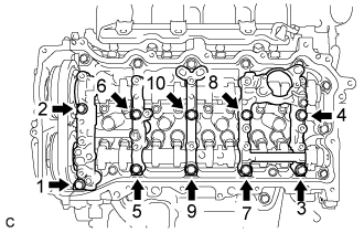 |
Remove the 10 bolts in several steps in the order shown in the illustration.
Remove the No. 1 camshaft bearing cap, No. 2 camshaft bearing cap, No. 3 camshaft bearing cap and No. 4 camshaft bearing cap.
| 29. REMOVE CAMSHAFT |
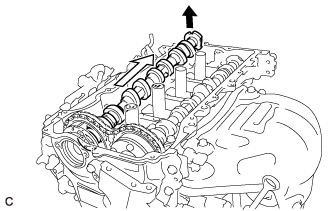 |
Raise the camshaft as shown in the illustration to remove it from the camshaft timing gear assembly.
| 30. REMOVE CAMSHAFT TIMING GEAR ASSEMBLY |
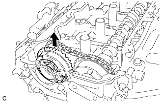 |
Remove the camshaft timing gear assembly.
| 31. REMOVE NO. 2 CAMSHAFT |
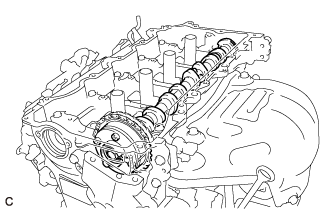 |
Hold up the chain sub-assembly and remove the No. 2 camshaft from the camshaft housing sub-assembly.
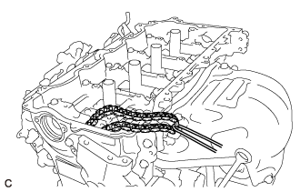 |
Suspend the chain sub-assembly with a string or equivalent as shown in the illustration.
| 32. REMOVE CAMSHAFT TIMING EXHAUST GEAR ASSEMBLY |
Secure the No. 2 camshaft in a vise by clamping the hexagonal part between aluminum plates.
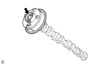 |
Remove the bolt and camshaft timing exhaust gear assembly.
| 33. REMOVE OIL CONTROL VALVE FILTER |
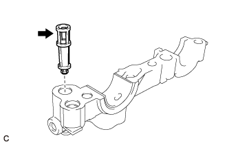 |
Remove the oil control valve filter from the No. 1 camshaft bearing cap.
| 34. REMOVE NO. 1 CAMSHAFT BEARING |
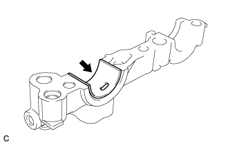 |
Remove the No. 1 camshaft bearing from the No. 1 camshaft bearing cap.
| 35. REMOVE NO. 2 CAMSHAFT BEARING |
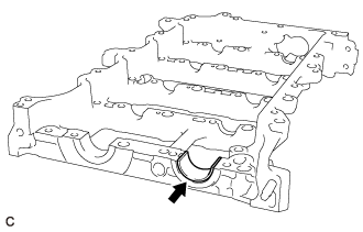 |
Remove the No. 2 camshaft bearing from the camshaft housing sub-assembly.