Home › Engine / Hybrid System ยท 6AR-FSE › ENGINE CONTROL › AIR FUEL RATIO SENSOR

AIR FUEL RATIO SENSOR > INSTALLATION

for Preparation Click here


1. INSTALL AIR FUEL RATIO SENSOR

HINT:
Perform "Inspection After Repair" after replacing the air fuel ratio sensor (Click here).


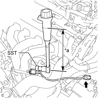
    A338571E01
  1. Using SST, install the air fuel ratio sensor to the exhaust manifold.
    Text in Illustration 
    *a
    Torque Wrench Fulcrum Length

    SST
    09224-00011  

    Torque:
    Specified tightening torque:
    44 N*m{ 449 kgf*cm , 32 ft.*lbf }

    NOTICE:
    If the air fuel ratio sensor has been struck or dropped, replace it.

    HINT:
    1. Calculate the torque wrench reading when changing the fulcrum length of the torque wrench (Click here).
    2. When using SST (fulcrum length of 30 mm (1.18 in.)) + torque wrench (fulcrum length of 260 mm (10.2 in.)): 39 N*m (398 kgf*cm, 29 ft.*lbf)

  1. Connect the air fuel ratio sensor connector.

  1. Engage the 3 wire harness clamps.


2. INSTALL NO. 1 EXHAUST MANIFOLD HEAT INSULATOR
  1. Install the No. 1 exhaust manifold heat insulator to the exhaust manifold converter sub-assembly (TWC: Front Catalyst) with the 4 bolts.

    Torque:
    12 N*m{ 122 kgf*cm , 9 ft.*lbf }


3. INSPECT FOR EXHAUST GAS LEAK
If gas is leaking, tighten the areas necessary to stop the leak. Replace damaged parts as necessary.
  1. Perform Inspection After Repair after repairing an exhaust gas leak (Click here).


4. PERFORM INITIALIZATION
(Click here)