INTERIOR PANELS / TRIM ROOF HEADLINING INSTALLATION
PROCEDURE

 1.INSTALL ROOF HEADLINING ASSEMBLY
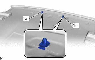
| *a | Clip (Black) |
| *b | Clip (White) |
Install the 2 clips to the roof headlining assembly.
Put the roof headlining assembly into the vehicle through the front door RH as shown in the illustration.
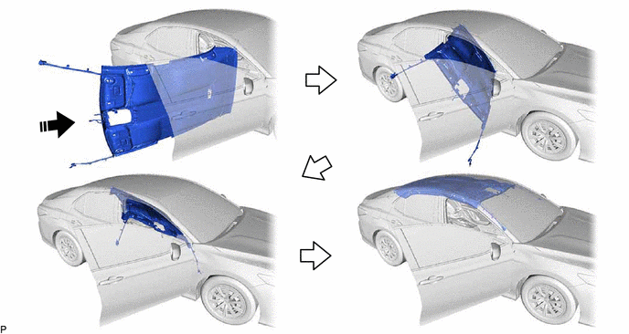

|
Install in this Direction | - | - |
- NOTICE:
-
Do not damage the roof headlining assembly or vehicle interior.
for Roof Side (for Normal Roof):
Engage the 2 claws to install the base of each visor holder.
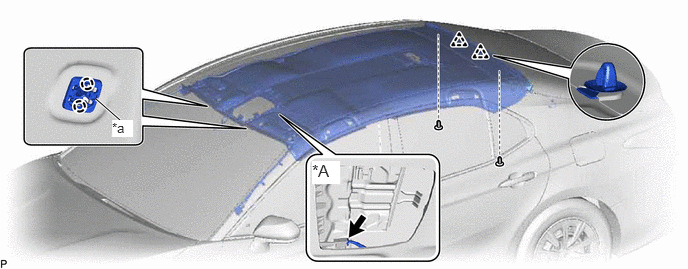
| *A | w/ Digital Television Antenna | - | - |
| *a | Base of Visor Holder | - | - |
Engage the 2 clips and install the roof headlining assembly with the 2 clips.
w/ Digital Television Antenna:
Connect the connector.
for Roof Side (for Panoramic Moon Roof):
Engage the guide and 14 fasteners.
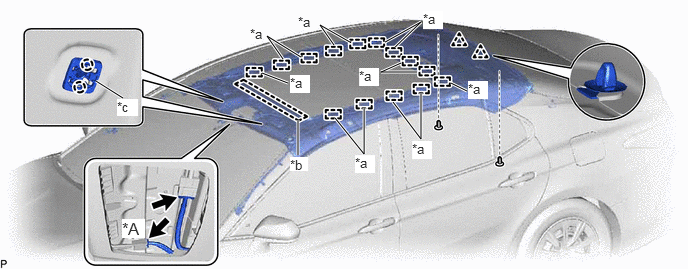
| *A | w/ Digital Television Antenna | - | - |
| *a | Fastener | *b | Guide |
| *c | Base of Visor Holder | - | - |
Engage the 2 claws to install the base of each visor holder.
Engage the 2 clips and install the roof headlining assembly with the 2 clips.
Connect each connector.
for Rear Pillar LH Side:
Engage the clamp.
Connect the connector.
for Rear Pillar RH Side:
Engage each clamp.
Connect each connector.
for Front Pillar LH Side:
Remove the protective cover.
Engage the 4 clamps.
Connect each connector.
Install the protective cover.
for Front Pillar RH Side:
Remove the protective cover.
Engage the 2 clamps.
Engage the guide.
Connect the connector bracket with the bolt.
- Torque:
- 7.0 N*m (71 kgf*cm, 62 in.*lbf)
Install the protective cover.
for Windshield Glass Side:
Connect each connector.
74348C
2.INSTALL VISOR HOLDER LH
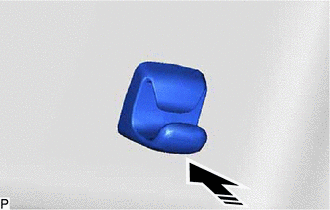
|
|
Install in this Direction |
Install the visor holder LH as shown in the illustration.
74320
3.INSTALL VISOR ASSEMBLY LH
- NOTICE:
-
Make sure to install the bracket with its arrow facing the front of the vehicle.
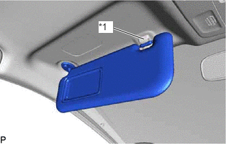
| *1 | Visor Holder LH |
Connect the visor assembly LH to the visor holder LH.
for "TORX" Screw:
Using a T25 "TORX" socket wrench, install the visor assembly LH with the 2 screws.
except "TORX" Screw:
Install the visor assembly LH with the 2 screws.
74318
4.INSTALL VISOR BRACKET COVER LH
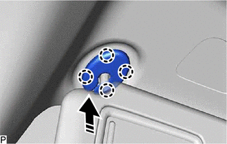
|
|
Install in this Direction |
Engage the 4 claws to install the visor bracket cover LH as shown in the illustration.
74348B
5.INSTALL VISOR HOLDER RH
- HINT:
-
Use the same procedure as for the LH side.
74310
6.INSTALL VISOR ASSEMBLY RH
- HINT:
-
Use the same procedure as for the LH side.
74317
7.INSTALL VISOR BRACKET COVER RH
- HINT:
-
Use the same procedure as for the LH side.
74610A
8.INSTALL ASSIST GRIP ASSEMBLY
- HINT:
-
Use the same procedure for the RH side and LH side.
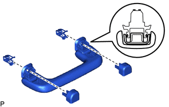
Install the 2 clips to the assist grip.
Temporarily install the 2 assist grip covers to the assist grip as shown in the illustration.
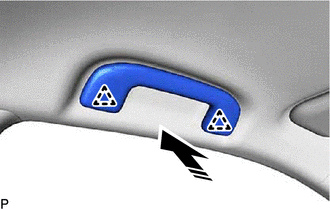
|
|
Install in this Direction |
Engage the 2 clips to install the assist grip assembly as shown in the illustration.
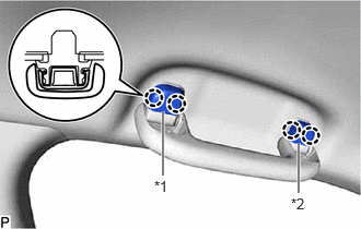
| *1 | Assist Grip Cover LH |
| *2 | Assist Grip Cover RH |
Engage the 4 claws to install the assist grip cover LH and assist grip cover RH.
- NOTICE:
-
Make sure that the clip is engaged securely.
74630E
9.INSTALL REAR ASSIST GRIP ASSEMBLY LH
- HINT:
-
Use the same procedure as for the assist grip assembly.
74620C
10.INSTALL REAR ASSIST GRIP ASSEMBLY RH
- HINT:
-
Use the same procedure as for the assist grip assembly.
86466D
11.INSTALL NO. 1 FORWARD RECOGNITION COVER (w/ Pre-collision System)
86466E
12.INSTALL NO. 2 FORWARD RECOGNITION COVER (w/ Pre-collision System)
87834
13.INSTALL INNER REAR VIEW MIRROR STAY HOLDER COVER (w/ Cover)
89943
14.INSTALL RAIN SENSOR COVER (w/ Rain Sensor)
81360T
15.INSTALL SPOT LIGHT ASSEMBLY
16.INSTALL ROOF CONSOLE BOX ASSEMBLY
17.INSTALL TRANSMISSION FLOOR SHIFT ASSEMBLY
for UA80E:
Click hereDrivetrain>UA80E (AUTOMATIC TRANSMISSION / TRANSAXLE)>SHIFT LEVER>INSTALLATION
for UB80E:
Click hereDrivetrain>UB80E (AUTOMATIC TRANSMISSION / TRANSAXLE)>SHIFT LEVER>INSTALLATION
for U760E:
Click hereDrivetrain>U760E (AUTOMATIC TRANSMISSION / TRANSAXLE)>SHIFT LEVER>INSTALLATION
18.INSTALL INSTRUMENT PANEL SAFETY PAD SUB-ASSEMBLY
62472A
19.INSTALL INNER ROOF SIDE GARNISH LH
Install 3 new clips to the inner roof side garnish LH.
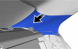
|
|
Install in this Direction |
Engage the 2 guides as shown in the illustration.
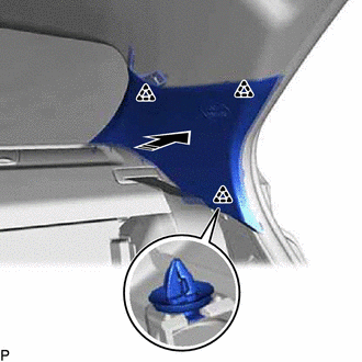
|
|
Install in this Direction |
Engage the 3 clips to install the inner roof side garnish LH as shown in the illustration.
62412B
20.INSTALL UPPER CENTER PILLAR GARNISH LH
Install a new clip to the upper center pillar garnish LH.
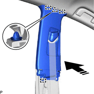
|
|
Install in this Direction |
Engage the 3 guides and clip as shown in the illustration.
Install the upper center pillar garnish LH with the 2 clips.
62414A
21.INSTALL LOWER CENTER PILLAR GARNISH LH
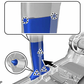
|
|
Install in this Direction |
Engage the 2 claws and 3 clips to install the lower center pillar garnish LH as shown in the illustration.
73220
22.CONNECT FRONT SEAT OUTER BELT ASSEMBLY LH
73233
23.INSTALL LAP BELT OUTER ANCHOR COVER (for LH Side)
62332A
24.INSTALL REAR DOOR OPENING TRIM WEATHERSTRIP LH
67918A
25.INSTALL REAR DOOR SCUFF PLATE LH
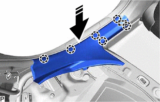
|
|
Install in this Direction |
Engage the guide and 6 claws to install the rear door scuff plate LH as shown in the illustration.
62212
26.INSTALL FRONT PILLAR GARNISH LH
Remove the protective cover.
Install a new clip to the front pillar garnish LH.
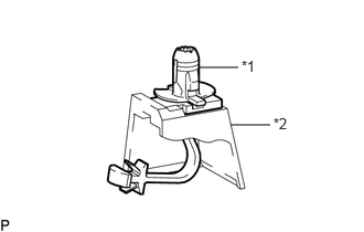
| *1 | Front Pillar Garnish Clip |
| *2 | Front Pillar Garnish LH |
Engage the front pillar garnish clip to the front pillar garnish LH.
- HINT:
-
Make sure that the front pillar garnish clip is engaged correctly.
w/o Front No. 3 Speaker:
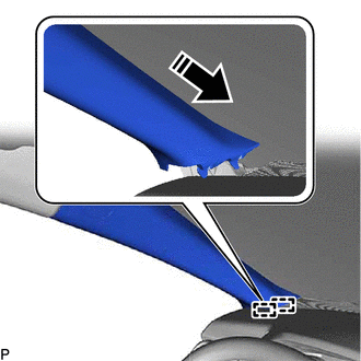
|
|
Install in this Direction |
Push the front pillar garnish LH as shown in the illustration to engage the 2 guides.
w/ Front No. 3 Speaker:
Connect the connector.
Push the front pillar garnish LH as shown in the illustration to engage the 2 guides.
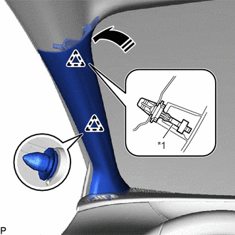
| *1 | Front Pillar Garnish Clip |
|
|
Install in this Direction |
Engage the clip and front pillar garnish clip to install the front pillar garnish LH as shown in the illustration.
- CAUTION:
-
Make sure to position the strap of the curtain shield airbag assembly LH below the engagement holes of the clips of front pillar garnish LH as shown in the illustration, otherwise the curtain shield airbag assembly LH will not be able to deploy properly.
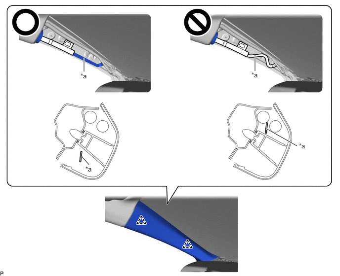 1.771,1.51 1.771,1.219 true 5.375,1.5 5.375,1.156 true 1.875,3.479 1.719,3.302 true 6.26,3.083 5.615,2.719 true 1.698,1.521 2.01,1.719 0.313,0.198 10 false *a 5.302,1.5 5.615,1.698 0.313,0.198 10 false *a 1.802,3.49 2.115,3.688 0.313,0.198 10 false *a 6.302,3 6.615,3.198 0.313,0.198 10 false *a
*a Position the Strap of the Curtain Shield Airbag Assembly LH - -
- HINT:
-
Make sure that the curtain shield airbag assembly LH is not pinched.
62312B
27.INSTALL FRONT DOOR OPENING TRIM WEATHERSTRIP LH
62112A
28.INSTALL COWL SIDE TRIM SUB-ASSEMBLY LH
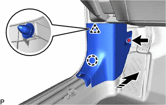
|
|
Install in this Direction |
Engage the claw and clip as shown in the illustration.
Install the cowl side trim sub-assembly LH with the clip.
67914
29.INSTALL FRONT DOOR SCUFF PLATE LH
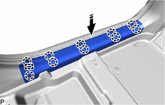
|
|
Install in this Direction |
Engage the guide and 10 claws to install the front door scuff plate LH as shown in the illustration.
62471A
30.INSTALL INNER ROOF SIDE GARNISH RH
- HINT:
-
Use the same procedure as for the LH side.
62411B
31.INSTALL UPPER CENTER PILLAR GARNISH RH
- HINT:
-
Use the same procedure as for the LH side.
62413A
32.INSTALL LOWER CENTER PILLAR GARNISH RH
- HINT:
-
Use the same procedure as for the LH side.
73210
33.CONNECT FRONT SEAT OUTER BELT ASSEMBLY RH
- HINT:
-
Use the same procedure as for the LH side.
73233
34.INSTALL LAP BELT OUTER ANCHOR COVER (for RH Side)
- HINT:
-
Use the same procedure as for the LH side.
62331A
35.INSTALL REAR DOOR OPENING TRIM WEATHERSTRIP RH
- HINT:
-
Use the same procedure as for the LH side.
67917A
36.INSTALL REAR DOOR SCUFF PLATE RH
- HINT:
-
Use the same procedure as for the LH side.
62211
37.INSTALL FRONT PILLAR GARNISH RH
- HINT:
-
Use the same procedure as for the LH side.
62311B
38.INSTALL FRONT DOOR OPENING TRIM WEATHERSTRIP RH
- HINT:
-
Use the same procedure as for the LH side.
62111A
39.INSTALL COWL SIDE TRIM SUB-ASSEMBLY RH
- HINT:
-
Use the same procedure as for the LH side.
67913
40.INSTALL FRONT DOOR SCUFF PLATE RH
- HINT:
-
Use the same procedure as for the LH side.
41.INSTALL REAR SEAT ASSEMBLY (for Fold Down Seat Type)
42.INSTALL REAR SEAT ASSEMBLY (for Reclining Seat Type)
43.INSTALL FRONT SEAT ASSEMBLY (for Manual Seat)
44.INSTALL FRONT SEAT ASSEMBLY (for Power Seat)