2GR-FKS ENGINE CONTROL CAMSHAFT POSITION SENSOR REMOVAL
CAUTION / NOTICE / HINT
The necessary procedures (adjustment, calibration, initialization or registration) that must be performed after parts are removed and installed, or replaced during VVT sensor removal/installation are shown below.
| Replaced Part or Performed Procedure | Necessary Procedure | Effect/Inoperative Function when Necessary Procedure not Performed | Link |
|---|---|---|---|
·
Replacement of throttle body with motor assembly ·
Cleaning the deposits from the throttle body with motor assembly |
Inspection after repair | ·
Poor idle, etc. ·
Engine start function, etc. |
( ) |
PROCEDURE

 17190
1.REMOVE INTAKE AIR SURGE TANK ASSEMBLY
11401Q
2.REMOVE VVT SENSOR (for Intake Side of Bank 1)
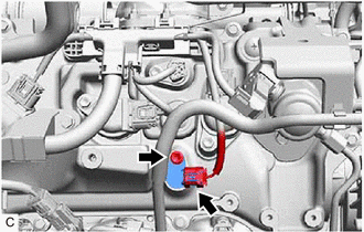
Disconnect the VVT sensor connector.
Remove the bolt and VVT sensor from the cylinder head cover sub-assembly.
- NOTICE:
-
If the VVT sensor has been struck or dropped, replace it.
11401M
3.REMOVE VVT SENSOR (for Exhaust Side of Bank 1)
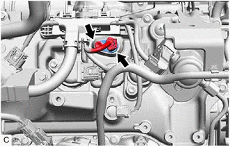
Disconnect the VVT sensor connector.
Remove the bolt and VVT sensor from the cylinder head cover sub-assembly.
- NOTICE:
-
If the VVT sensor has been struck or dropped, replace it.
11401M
4.REMOVE VVT SENSOR (for Intake Side of Bank 2)
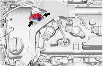
Disconnect the VVT sensor connector.
Remove the bolt and VVT sensor from the cylinder head cover sub-assembly LH.
- NOTICE:
-
If the VVT sensor has been struck or dropped, replace it.
11401M
5.REMOVE VVT SENSOR (for Exhaust Side of Bank 2)
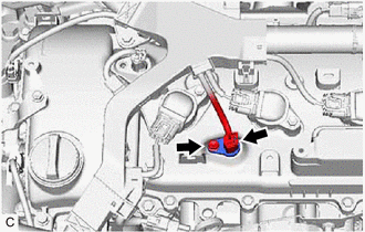
Disconnect the VVT sensor connector.
Remove the bolt and VVT sensor from the cylinder head cover sub-assembly LH.
- NOTICE:
-
If the VVT sensor has been struck or dropped, replace it.