2AR-FE INTAKE / EXHAUST INTAKE SYSTEM ON-VEHICLE INSPECTION
CAUTION / NOTICE / HINT
The necessary procedures (adjustment, calibration, initialization, or registration) that must be performed after parts are removed, installed, or replaced when repairing air leaks in the intake system are shown below.
| Replacement Part or Procedure | Necessary Procedures | Effects/Inoperative when not Performed | Link |
|---|---|---|---|
| Air leak from intake system is repaired | Inspection After Repair | ·
Poor idle, etc. ·
Engine start function, etc. |
( ) |
PROCEDURE

 1.INSPECT INTAKE SYSTEM
- CAUTION:
-
-
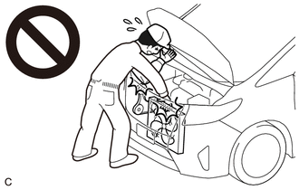
To prevent injury due to contact with an operating V-ribbed belt or cooling fan, keep your hands and clothing away from the V-ribbed belt and cooling fans when working in the engine compartment with the engine running or the engine switch on (IG).
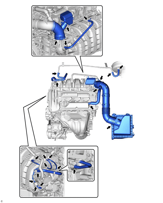
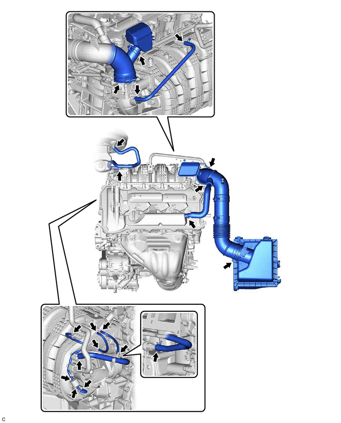
Check that there are no vacuum leaks at the points shown in the illustration.
- HINT:
-
Perform "Inspection After Repair" after repairing air leaks in the intake system.
-
Click hereEngine / Hybrid System>2AR-FE (ENGINE CONTROL)>SFI SYSTEM>INITIALIZATION
for LHD
for RHD
2.INSPECT INTAKE AIR CONTROL VALVE (for ACIS)
- CAUTION:
-
To prevent injury due to contact with an operating V-ribbed belt or cooling fan, keep your hands and clothing away from the V-ribbed belt and cooling fans when working in the engine compartment with the engine running or the engine switch on (IG).
Connect the GTS to the DLC3.
Turn the engine switch on (IG).
Turn the GTS on.
Enter the following menus: Powertrain / Engine and ECT / Active Test / Activate the VSV for Intake Control.
- Powertrain > Engine and ECT > Active Test
-
Tester Display Activate the VSV for Intake Control - 50004 234 3
When Activate the VSV for Intake Control is set to on, check that the actuator rod operates.
If the actuator rod does not operate, inspect the intake air control valve (for ACIS), vacuum tank and check valve.
Click hereEngine / Hybrid System>2AR-FE (INTAKE / EXHAUST)>INTAKE MANIFOLD>INSPECTION
When Activate the VSV for Intake Control is set to off, check that the actuator rod returns to its original position.
If the actuator rod does not return to its original position, inspect the intake air control valve (for ACIS) and vacuum hose.
Click hereEngine / Hybrid System>2AR-FE (INTAKE / EXHAUST)>INTAKE MANIFOLD>INSPECTION
17335
3.INSPECT INTAKE AIR CONTROL VALVE ACTUATOR (for TCV)
- CAUTION:
-
To prevent injury due to contact with an operating V-ribbed belt or cooling fan, keep your hands and clothing away from the V-ribbed belt and cooling fans when working in the engine compartment with the engine running or the engine switch on (IG).
Connect the GTS to the DLC3.
Turn the engine switch on (IG).
Turn the GTS on.
Enter the following menus: Powertrain / Engine and ECT / Active Test / Control the IAC Duty Ratio.
- Powertrain > Engine and ECT > Active Test
-
Active Test Display Control the IAC Duty Ratio -
Data List Display Intake Air Control Position - 50004 234 150 161
Set the duty ratio to 60% or -60% for 1 to 3 seconds, and then return the duty ratio to 0%. Check the Data List item Intake Air Control Position.
- Standard:
Condition (Active Test) Specified Condition (Data List) Control the IAC Duty Ratio set to 60% Intake Air Control Position 35° or more Control the IAC Duty Ratio set to -60% Intake Air Control Position 17° or less
- NOTICE:
- ·
Supply power to the intake air control valve actuator (for TCV) for 1 to 3 seconds.
·If power is supplied to the intake air control valve actuator (for TCV) for less than 1 second, the gear of the tumble control valve (TCV) does not reach the stopper and the value in the Data List may be incorrect.
·If power is supplied to the intake air control valve actuator (for TCV) for more than 3 seconds, the motor may be damaged.
·Do not perform this inspection more than 2 times consecutively.
- HINT:
-
The standard duty ratio for inspections is 60% or -60%. However, if the value in the Data List is not as specified, set the duty ratio to 100% or -100% for 1 to 3 seconds, and check the value in the Data List again.
- Standard:
Condition (Active Test) Specified Condition (Data List) Control the IAC Duty Ratio set to 100% Intake Air Control Position 70° or more Control the IAC Duty Ratio set to -100% Intake Air Control Position 2° or less
If the result is not as specified, perform the following inspection.
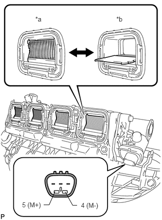
| *a | Closed |
| *b | Open |
Remove the intake manifold.
- HINT:
-
When the intake manifold is removed, the 4 tumble control valves (TCV) are half open.
Click hereEngine / Hybrid System>2AR-FE (INTAKE / EXHAUST)>INTAKE MANIFOLD>REMOVAL
Check that the 4 tumble control valves (TCV) move when the battery is connected to the terminals of the intake air control valve actuator (for TCV).
- Standard:
Tester Connection Specified Condition Positive (+) battery voltage applied to terminal 4 (M-), and negative (-) battery voltage applied to terminal 5 (M+) Open → Closed Positive (+) battery voltage applied to terminal 5 (M+), and negative (-) battery voltage applied to terminal 4 (M-) Closed → Open
- NOTICE:
- ·
Apply battery voltage for 1 to 3 seconds.
·If battery voltage is applied for more than 3 seconds, the intake air control valve actuator (for TCV) may be damaged.
·Do not allow the lead wires to contact the other terminals.
If the result is not as specified, perform the following inspections:
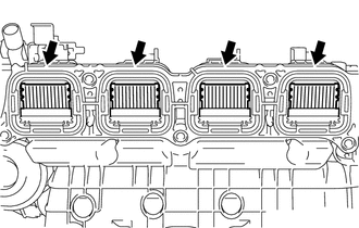
Check that the 4 tumble control valves (TCV) are not cracked or deformed.
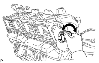
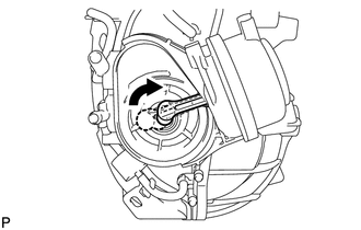
Remove the intake air control valve actuator (for TCV), turn the gear of the 4 tumble control valves (TCV) and check that the 4 tumble control valves (TCV) move smoothly.
Click hereEngine / Hybrid System>2AR-FE (INTAKE / EXHAUST)>INTAKE AIR CONTROL VALVE ACTUATOR (for TCV)>REMOVAL
If the 4 tumble control valves (TCV) move smoothly, inspect the intake air control valve actuator (for TCV).
4.PERFORM INITIALIZATION
Perform Inspection After Repair after repairing any vacuum leaks in the intake system.
Click hereEngine / Hybrid System>2AR-FE (ENGINE CONTROL)>SFI SYSTEM>INITIALIZATION