A25A-FKS BATTERY / CHARGING GENERATOR INSTALLATION
CAUTION / NOTICE / HINT
- NOTICE:
-
This procedure includes the installation of small-head bolts. Refer to Small-Head Bolts of Basic Repair Hint to identify the small-head bolts.
-
Click hereGeneral>INTRODUCTION>REPAIR INSTRUCTION>PRECAUTION
PROCEDURE

 27020
1.INSTALL GENERATOR ASSEMBLY
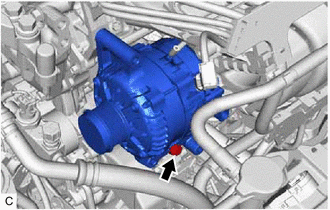
Temporarily install the generator assembly with the bolt.
Using an E8 "TORX" socket wrench, install the 2 stud bolts.
- Torque:
- 9.8 N*m (100 kgf*cm, 87 in.*lbf)
Install the generator assembly with the bolt and 2 nuts.
- Torque:
- 25 N*m (255 kgf*cm, 18 ft.*lbf)
Install the wire harness clamp bracket to the generator assembly with the bolt.
- Torque:
- 10 N*m (102 kgf*cm, 7 ft.*lbf)
Connect the wire harness to terminal B with the nut.
- Torque:
- 9.8 N*m (100 kgf*cm, 87 in.*lbf)
Close the terminal cap.
Connect the generator assembly connector.
2.INSTALL V-RIBBED BELT
89421
3.INSTALL E.F.I. VACUUM SENSOR ASSEMBLY (MANIFOLD ABSOLUTE PRESSURE SENSOR)
17750A
4.INSTALL INLET AIR CLEANER ASSEMBLY
53295E
5.INSTALL COOL AIR INTAKE DUCT SEAL
6.CONNECT CABLE TO NEGATIVE BATTERY TERMINAL