MAINTENANCE BRAKE VACUUM HOSE(for RHD) INSTALLATION
PROCEDURE

 44773F
1.INSTALL UNION TO CHECK VALVE HOSE (for 2AR-FE)
Install the 2 clips to the union to check valve hose.
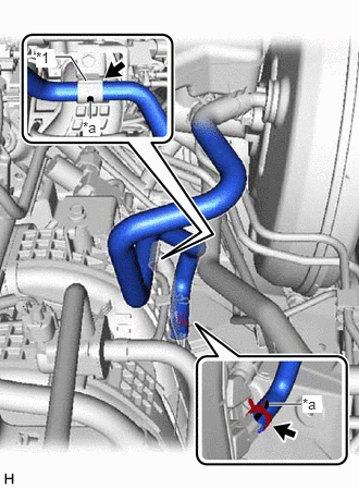
| *1 | Vacuum Hose Clamp |
| *a | Paint Mark |
Connect the union to check valve hose to the intake manifold and slide the clip to secure it.
- NOTICE:
- ·
When connecting the union to check valve hose, face the paint mark up.
·Make sure that the tabs of the clip are facing upward.
Install the union to check valve hose to the vacuum hose clamp.
- NOTICE:
-
When installing the union to check valve hose to the vacuum hose clamp, make sure to align the paint mark with the vacuum hose clamp as shown in the illustration.
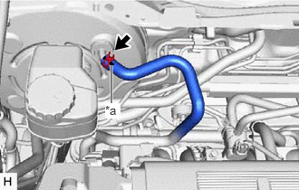
| *a | Paint Mark |
Connect the union to check valve hose to the brake booster assembly and slide the clip to secure it.
- NOTICE:
- ·
When connecting the union to check valve hose, face the paint mark up.
·Make sure that the tabs of the clip are facing upward.
17361M
2.INSTALL AIR TUBE (for 2GR-FKS)
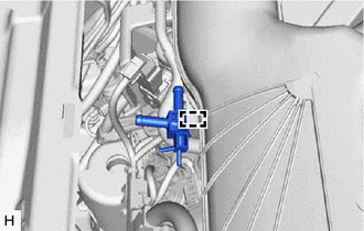
Engage the clamp to install the air delivery way to the intake air surge tank assembly.
Install the 2 clips to the air tube.
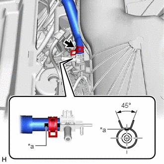
| *a | Paint Mark |
Connect the air tube to the air delivery way and slide the clip to secure it.
- NOTICE:
- ·
Make sure to position the paint mark of the air tube as shown in the illustration.
·Make sure that the tabs of the clip are aligned as shown in the illustration.
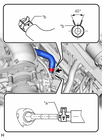
| *a | Paint Mark |
| *b | Dot Paint |
Connect the air tube to the vacuum pump assembly and slide the clip to secure it.
- NOTICE:
- ·
Make sure to position the paint mark of the air tube as shown in the illustration.
·Make sure that the tabs of the clip are aligned as shown in the illustration.
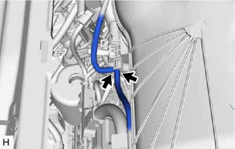
Connect the 2 vacuum transmitting hose assemblies to the air delivery way.
44773F
3.INSTALL UNION TO CHECK VALVE HOSE (for 2GR-FKS)
Install the 2 clips to the union to check valve hose.
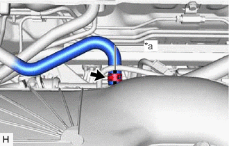
| *a | Paint Mark |
Connect the union to check valve hose to the air delivery way and slide the clip to secure it.
- NOTICE:
- ·
When connecting the union to check valve hose, face the paint mark up.
·Make sure that the tabs of the clip are facing upward.
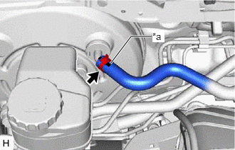
| *a | Paint Mark |
Connect the union to check valve hose to the brake booster assembly and slide the clip to secure it.
- NOTICE:
- ·
When connecting the union to check valve hose, face the paint mark up.
·Make sure that the tabs of the clip are facing upward.
53607A
4.INSTALL FRONT CENTER UPPER SUSPENSION BRACE SUB-ASSEMBLY
55708
5.INSTALL COWL TOP VENTILATOR LOUVER SUB-ASSEMBLY