Home › Engine / Hybrid System › CRUISE CONTROL › LANE DEPARTURE ALERT SYSTEM (w/ Steering Control) › 2017.12–2021.02
RM33A0E _51 Engine / Hybrid System _065357 CRUISE CONTROL _0319643 LANE DEPARTURE ALERT SYSTEM(w/ Steering Control) J

CRUISE CONTROL  LANE DEPARTURE ALERT SYSTEM(w/ Steering Control)  Steering Pad Switch Circuit  


DESCRIPTION

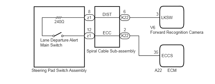
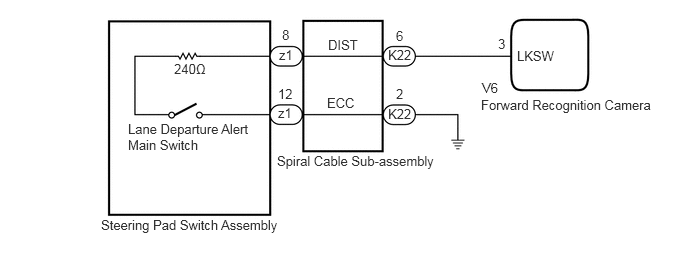
The forward recognition camera receives a lane departure alert main switch signal from the steering pad switch assembly.

WIRING DIAGRAM
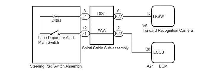
for A25A-FKS:
A401977E02
1.813,0.635 2.427,0.833 0.615,0.198 10 false 240Ω 1.344,1.25 2.625,1.677 1.281,0.427 10 false Lane Departure Alert Main Switch 1.052,2.26 5.333,2.458 4.281,0.198 10 false Steering Pad Switch Assembly 2.885,1.615 6.708,1.813 3.823,0.198 10 false Spiral Cable Sub-assembly 5.01,0.99 6.865,1.208 1.854,0.219 10 false Forward Recognition Camera 5.01,0.833 5.469,1.031 0.458,0.198 10 false V6 2.906,0.5 3.219,0.698 0.313,0.198 10 false z1 2.896,1.104 3.208,1.302 0.313,0.198 10 false z1 2.938,0.302 3.094,0.5 0.156,0.198 10 false 8 2.896,0.906 3.104,1.104 0.208,0.198 10 false 12 3.417,0.396 4.031,0.594 0.615,0.198 10 false DIST 3.427,1.01 3.885,1.208 0.458,0.198 10 false ECC 4.042,0.5 4.5,0.698 0.458,0.198 10 false K22 4.042,1.104 4.5,1.302 0.458,0.198 10 false K22 4.115,0.302 4.427,0.5 0.313,0.198 10 false 6 4.125,0.906 4.313,1.083 0.188,0.177 10 false 2 5.208,0.385 5.365,0.583 0.156,0.198 10 false 3 5.375,0.5 5.99,0.698 0.615,0.198 10 false LKSW 5.156,2.26 5.615,2.458 0.458,0.198 10 false A24 5.583,2.26 6.042,2.458 0.458,0.198 10 false ECM 5.385,1.771 6,1.969 0.615,0.198 10 false ECCS 5.125,1.656 5.583,1.854 0.458,0.198 10 false 28

for 2AR-FE:
A401977E03
1.813,0.635 2.427,0.833 0.615,0.198 10 false 240Ω 1.344,1.25 2.625,1.677 1.281,0.427 10 false Lane Departure Alert Main Switch 1.052,2.26 5.333,2.458 4.281,0.198 10 false Steering Pad Switch Assembly 2.885,1.615 6.708,1.813 3.823,0.198 10 false Spiral Cable Sub-assembly 5.01,0.99 6.865,1.208 1.854,0.219 10 false Forward Recognition Camera 5.01,0.833 5.469,1.031 0.458,0.198 10 false V6 2.906,0.5 3.219,0.698 0.313,0.198 10 false z1 2.896,1.104 3.208,1.302 0.313,0.198 10 false z1 2.938,0.302 3.094,0.5 0.156,0.198 10 false 8 2.896,0.906 3.104,1.104 0.208,0.198 10 false 12 3.417,0.396 4.031,0.594 0.615,0.198 10 false DIST 3.427,1.01 3.885,1.208 0.458,0.198 10 false ECC 4.042,0.5 4.5,0.698 0.458,0.198 10 false K22 4.042,1.104 4.5,1.302 0.458,0.198 10 false K22 4.115,0.302 4.427,0.5 0.313,0.198 10 false 6 4.125,0.906 4.313,1.083 0.188,0.177 10 false 2 5.208,0.385 5.365,0.583 0.156,0.198 10 false 3 5.375,0.5 5.99,0.698 0.615,0.198 10 false LKSW 5.156,2.26 5.615,2.458 0.458,0.198 10 false A22 5.583,2.26 6.042,2.458 0.458,0.198 10 false ECM 5.385,1.771 6,1.969 0.615,0.198 10 false ECCS 5.125,1.656 5.583,1.854 0.458,0.198 10 false 35

for 2GR-FKS:
A418961E01
1.813,0.635 2.427,0.833 0.615,0.198 10 false 240Ω 1.052,2.26 5.333,2.458 4.281,0.198 10 false Steering Pad Switch Assembly 2.885,1.594 4.833,1.927 1.948,0.333 10 false Spiral Cable Sub-assembly 1.333,1.26 2.625,1.688 1.292,0.427 10 false Lane Departure Alert Main Switch 5.01,1.01 6.802,1.458 1.792,0.448 10 false Forward Recognition Camera 5.385,0.5 6,0.698 0.615,0.198 10 false LKSW 5.188,0.375 5.802,0.573 0.615,0.198 10 false 3 4.042,0.49 4.656,0.688 0.615,0.198 10 false K22 4.125,0.292 4.74,0.49 0.615,0.198 10 false 6 4.125,0.896 4.74,1.094 0.615,0.198 10 false 2 4.042,1.104 4.656,1.302 0.615,0.198 10 false K22 3.406,0.99 4.021,1.188 0.615,0.198 10 false ECC 3.417,0.385 4.031,0.583 0.615,0.198 10 false DIST 2.906,0.49 3.521,0.688 0.615,0.198 10 false z1 2.938,0.281 3.552,0.479 0.615,0.198 10 false 8 2.896,0.896 3.51,1.094 0.615,0.198 10 false 12 2.896,1.094 3.51,1.292 0.615,0.198 10 false z1 5.021,0.833 5.635,1.031 0.615,0.198 10 false V6

CAUTION / NOTICE / HINT

NOTICE:

The vehicle is equipped with a Supplemental Restraint System (SRS) which includes components such as airbags. Before servicing (including removal or installation of parts), be sure to read the precaution for Supplemental Restraint System.

Click hereVehicle Interior>SUPPLEMENTAL RESTRAINT SYSTEMS>AIRBAG SYSTEM>PRECAUTION


PROCEDURE

1.INSPECT STEERING PAD SWITCH ASSEMBLY
a.

Remove the steering pad switch assembly.

Click hereSteering>STEERING COLUMN>STEERING PAD SWITCH>REMOVAL


b.

Inspect the steering pad switch assembly.

Click hereSteering>STEERING COLUMN>STEERING PAD SWITCH>INSPECTION


Result:
Proceed to
OK
NG


OK

2.INSPECT SPIRAL CABLE SUB-ASSEMBLY

NG

REPLACE STEERING PAD SWITCH ASSEMBLY

2.INSPECT SPIRAL CABLE SUB-ASSEMBLY
a.

Remove the spiral cable sub-assembly.

Click hereVehicle Interior>SUPPLEMENTAL RESTRAINT SYSTEMS>SPIRAL CABLE>REMOVAL


b.

Inspect the spiral cable sub-assembly.

Click hereVehicle Interior>SUPPLEMENTAL RESTRAINT SYSTEMS>SPIRAL CABLE>INSPECTION


Result:
Proceed to
OK
NG


OK

3.CHECK HARNESS AND CONNECTOR (SPIRAL CABLE SUB-ASSEMBLY - FORWARD RECOGNITION CAMERA)

NG

3.CHECK HARNESS AND CONNECTOR (SPIRAL CABLE SUB-ASSEMBLY - FORWARD RECOGNITION CAMERA)
a.

Disconnect the K22 spiral cable sub-assembly connector.


b.

Disconnect the V6 forward recognition camera connector.


c.

Measure the resistance according to the value(s) in the table below.

Standard Resistance:
Tester Connection Condition Specified Condition
K22-6 (DIST) - V6-3 (LKSW) Always Below 1 Ω
K22-6 (DIST) or V6-3 (LKSW) - Body ground Always 10 kΩ or higher


d.

Connect the V6 forward recognition camera connector.


e.

Connect the K22 spiral cable sub-assembly connector.


Result:
Proceed to
OK
NG


OK

4.CHECK HARNESS AND CONNECTOR (SPIRAL CABLE SUB-ASSEMBLY - ECM OR BODY GROUND)

NG

REPAIR OR REPLACE HARNESS OR CONNECTOR

4.CHECK HARNESS AND CONNECTOR (SPIRAL CABLE SUB-ASSEMBLY - ECM OR BODY GROUND)
a.

for A25A-FKS:

i.

Disconnect the K22 spiral cable sub-assembly connector.


ii.

Disconnect the A24 ECM connector.


iii.

Measure the resistance according to the value(s) in the table below.

Standard Resistance:
Tester Connection Condition Specified Condition
K22-2 (ECC) - A24-28 (ECCS) Always Below 1 Ω
K22-2 (ECC) or A24-28 (ECCS) - Body ground Always 10 kΩ or higher


iv.

Connect the A24 ECM connector.


v.

Connect the K22 spiral cable sub-assembly connector.


b.

for 2AR-FE:

i.

Disconnect the K22 spiral cable sub-assembly connector.


ii.

Disconnect the A22 ECM connector.


iii.

Measure the resistance according to the value(s) in the table below.

Standard Resistance:
Tester Connection Condition Specified Condition
K22-2 (ECC) - A22-35 (ECCS) Always Below 1 Ω
K22-2 (ECC) or A22-35 (ECCS) - Body ground Always 10 kΩ or higher


iv.

Connect the A22 ECM connector.


v.

Connect the K22 spiral cable sub-assembly connector.


c.

for 2GR-FKS:

i.

Disconnect the K22 spiral cable sub-assembly connector.


ii.

Measure the resistance according to the value(s) in the table below.

Standard Resistance:
Tester Connection Condition Specified Condition
K22-2 (ECC) - Body ground Always Below 1 Ω


iii.

Connect the K22 spiral cable sub-assembly connector.


Result:
Proceed to
OK
NG


OK

PROCEED TO NEXT SUSPECTED AREA SHOWN IN PROBLEM SYMPTOMS TABLE

NG

REPAIR OR REPLACE HARNESS OR CONNECTOR