THEFT DETERRENT / KEYLESS ENTRY THEFT DETERRENT SYSTEM Ignition Switch Circuit
DESCRIPTION
The main body ECU (multiplex network body ECU) determines the ignition switch position (LOCK, ACC, ON) based on signals from the IG and ACC circuit.
WIRING DIAGRAM
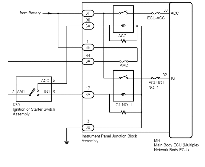
CAUTION / NOTICE / HINT
- NOTICE:
- ·
Inspect the fuses for circuits related to this system before performing the following procedure.
·The vehicle battery supplies power to the main body ECU (multiplex network body ECU) via the door control battery. Therefore, before performing this troubleshooting procedure, make sure to perform an on-vehicle inspection to confirm that the main body ECU (multiplex network body ECU) power source circuit is normal.*
Click hereVehicle Interior>DOOR LOCK>POWER DOOR LOCK CONTROL SYSTEM>ON-VEHICLE INSPECTION
*: w/ Door Control Battery
PROCEDURE
Connect the GTS to the DLC3.
Turn the ignition switch to ON.
Turn the GTS on.
Enter the following menus: Body Electrical / Main Body / Data List.
Read the Data List according to the display on the GTS.
- Body Electrical > Main Body > Data List
-
Tester Display Measurement Item Range Normal Condition Diagnostic Note ACC SW Ignition switch OFF or ON OFF: Ignition switch off
ON: Ignition switch ACC- IG SW Ignition switch OFF or ON OFF: Ignition switch off or ACC
ON: Ignition switch ON-
- Body Electrical > Main Body > Data List
-
Tester Display ACC SW IG SW - 50003 123 31,30
- OK:
The GTS display changes correctly in response to the ignition switch state.
- Result:
Proceed to OK NG
OK
Click hereVehicle Interior>THEFT DETERRENT / KEYLESS ENTRY>THEFT DETERRENT SYSTEM>PROBLEM SYMPTOMS TABLE
NG
Remove the ignition or starter switch assembly.
for 2AR-FE: Click hereEngine / Hybrid System>2AR-FE (STARTING)>IGNITION SWITCH>REMOVAL
for A25A-FKS: Click hereEngine / Hybrid System>A25A-FKS (STARTING)>IGNITION SWITCH>REMOVAL
Inspect the ignition or starter switch assembly.
for 2AR-FE: Click hereEngine / Hybrid System>2AR-FE (STARTING)>IGNITION SWITCH>INSPECTION
for A25A-FKS: Click hereEngine / Hybrid System>A25A-FKS (STARTING)>IGNITION SWITCH>INSPECTION
- Result:
Result Proceed to OK A NG (for 2AR-FE) B NG (for A25A-FKS) C
A
B
C
Disconnect the 3F and 3E instrument panel junction block assembly connectors.
Measure the voltage according to the value(s) in the table below.
- Standard Voltage:
Tester Connection Condition Specified Condition 3F-1 - Body ground Always 11 to 14 V 3E-1 - Body ground Always 11 to 14 V
- Result:
Proceed to OK NG
OK
NG
Disconnect the 3B instrument panel junction block assembly connector.
Measure the resistance according to the value(s) in the table below.
- Standard Resistance:
Tester Connection Condition Specified Condition 3B-3 - Body ground Always Below 1 Ω
- Result:
Proceed to OK NG
OK
NG
Disconnect the 3A instrument panel junction block assembly connector.
Measure the resistance according to the value(s) in the table below.
- Standard Resistance:
Tester Connection Condition Specified Condition K30-8 (IG1) - 3A-17 Always Below 1 Ω K30-6 (ACC) - 3A-30 Always Below 1 Ω K30-7 (AM1) - 3A-44 Always Below 1 Ω K30-8 (IG1) or 3A-17 - Other terminals and body ground Always 10 kΩ or higher K30-6 (ACC) or 3A-30 - Other terminals and body ground Always 10 kΩ or higher K30-7 (AM1) or 3A-44 - Other terminals and body ground Always 10 kΩ or higher
- Result:
Proceed to OK NG
OK
NG
Temporarily replace the instrument panel junction block assembly with a new or known good one.
Click herePower Source / Network>POWER DISTRIBUTION>MAIN BODY ECU>REMOVAL
- Result:
Proceed to NEXT
NEXT
Check the active arming mode function.
Click hereVehicle Interior>THEFT DETERRENT / KEYLESS ENTRY>THEFT DETERRENT SYSTEM>SYSTEM DESCRIPTION
- OK:
The active arming mode function operates normally.
- Result:
Proceed to OK NG
OK
NG