SEAT FRONT POWER SEAT CONTROL SYSTEM(w/ Memory) Power Seat does not Return to Memorized Position
DESCRIPTION
When the M1 or M2 switch of the seat memory switch is pressed, the outer mirror control ECU assembly sends a switch signal to the main body ECU (multiplex network body ECU) via CAN communication. Then, the main body ECU (multiplex network body ECU) sends a recall request signal to the position control ECU assembly. The position control ECU assembly operates each motor to move the seat to the memorized position.
WIRING DIAGRAM
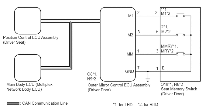
CAUTION / NOTICE / HINT
- NOTICE:
- ·
The seat position will not be stored if the SET switch and 2 or more of the seat memory switches (for example, M1 switch and M2 switch) are pressed simultaneously.
If a memorizing operation has failed, release all of the switches. The seat memory function will not operate unless the switches are released.
·The seat will not return to the memorized position if 2 or more of the seat memory switches (for example, M1 switch and M2 switch) are pressed simultaneously.
If a restoring operation has failed, release all of the switches. The seat memory restoring function will not operate unless the switches are released.
·The front power seat control system (w/ Memory) uses the CAN communication system. First, confirm that there are no malfunctions in the CAN communication system. Refer to How to Proceed with Troubleshooting.
·Before replacing the main body ECU (multiplex network body ECU), refer to Service Bulletin.
·The vehicle battery supplies power to the main body ECU (multiplex network body ECU) via the door control battery. Therefore, before performing this troubleshooting procedure, make sure to perform an on-vehicle inspection to confirm that the main body ECU (multiplex network body ECU) power source circuit is normal.
Click hereVehicle Interior>DOOR LOCK>POWER DOOR LOCK CONTROL SYSTEM>ON-VEHICLE INSPECTION
PROCEDURE
Check that each function of the power seat operates normally by using the front power seat switch (driver seat).
Click hereVehicle Interior>SEAT>FRONT POWER SEAT CONTROL SYSTEM (w/ Memory)>OPERATION CHECK
- OK:
Each function of the power seat operates normally using the front power seat switch (driver seat).
- Result:
Proceed to OK NG
OK
NG
Check the seat position memory function.
Click hereVehicle Interior>SEAT>FRONT POWER SEAT CONTROL SYSTEM (w/ Memory)>OPERATION CHECK
- OK:
Seat position memory function is normal.
- Result:
Proceed to OK NG
OK
NG
Under each of the following conditions, check that the seat position restoring function operates by pressing the M1 or M2 switch.
Click hereVehicle Interior>SEAT>FRONT POWER SEAT CONTROL SYSTEM (w/ Memory)>OPERATION CHECK
The engine switch is on (IG), and the shift lever is in P.*1
Within 180 seconds after the driver door is opened with the engine switch off.*2
Within 60 seconds after the driver door is opened and then closed with the engine switch off.*3
- Result:
Result Proceed to Seat position restoring function does not operate at all. A Seat position restoring function does not operate when the condition is *1. B ·Seat position restoring function does not operate when the condition is *2.
·Seat position restoring function does not operate when the condition is *3.
C
A
B
C
Store a seat position in memory for the M1 and M2 switches.
Click hereVehicle Interior>SEAT>FRONT POWER SEAT CONTROL SYSTEM (w/ Memory)>OPERATION CHECK
Connect the GTS to the DLC3.
Turn the engine switch on (IG).
Turn the GTS on.
Enter the following menus: Body Electrical / Driver Seat / Data List.
Read the Data List according to the display on the GTS.
- Body Electrical > Driver Seat > Data List
-
Tester Display Measurement Item Range Normal Condition Diagnostic Note Seat Memory No1 Seat position memorized with M1 switch Mem or Not Mem Mem: Memorized
Not Mem: Not memorized- Seat Memory No2 Seat position memorized with M2 switch Mem or Not Mem Mem: Memorized
Not Mem: Not memorized-
- Body Electrical > Driver Seat > Data List
-
Tester Display Seat Memory No1 Seat Memory No2 - 50003 162 3,4
- OK:
Mem is displayed on the GTS screen.
- Result:
Proceed to OK NG
OK
NG
Replace the outer mirror control ECU assembly (driver door) with a new or known good one.
Click hereVehicle Exterior>MIRROR (EXT)>OUTER MIRROR CONTROL ECU>REMOVAL
- Result:
Proceed to NEXT
NEXT
Check the seat position memory and restoring functions.
Click hereVehicle Interior>SEAT>FRONT POWER SEAT CONTROL SYSTEM (w/ Memory)>OPERATION CHECK
- OK:
Seat position memory and restoring functions operate normally.
- Result:
Proceed to OK NG
OK
NG
Connect the GTS to the DLC3.
Turn the engine switch on (IG).
Turn the GTS on.
Enter the following menus: Powertrain / Engine and ECT / Data List. (for 2AR-FE)
Read the Data List according to the display on the GTS.
- Powertrain > Engine and ECT > Data List
-
Tester Display Measurement Item Range Normal Condition Diagnostic Note Shift SW Status (P Range) Park/neutral position switch status ON or OFF ON: Shift lever in P
OFF: Shift lever not in P-
- Powertrain > Engine and ECT > Data List
-
Tester Display Shift SW Status (P Range) - 50003 234 125
- OK:
On the GTS screen, ON or OFF is displayed accordingly.
Enter the following menus: Powertrain / Engine / Data List. (for 2GR-FKS)
Read the Data List according to the display on the GTS.
- Powertrain > Engine > Data List
-
Tester Display Measurement Item Range Normal Condition Diagnostic Note Shift SW Status (P Range) Park/neutral position switch status ON or OFF ON: Shift lever in P
OFF: Shift lever not in P-
- Powertrain > Engine > Data List
-
Tester Display Shift SW Status (P Range) - 50003 372 15
- OK:
On the GTS screen, ON or OFF is displayed accordingly.
- Result:
Proceed to OK NG
OK
NG
for U760E: Click hereDrivetrain>U760E (AUTOMATIC TRANSMISSION / TRANSAXLE)>AUTOMATIC TRANSAXLE SYSTEM>P0705
for UA80E: Click hereDrivetrain>UA80E (AUTOMATIC TRANSMISSION / TRANSAXLE)>AUTOMATIC TRANSAXLE SYSTEM>P070513
Replace the position control ECU assembly (driver seat) with a new or known good one.
Click hereVehicle Interior>SEAT>POWER SEAT CONTROL ECU>REMOVAL
- Result:
Proceed to NEXT
NEXT
Check the seat position memory and restoring functions.
Click hereVehicle Interior>SEAT>FRONT POWER SEAT CONTROL SYSTEM (w/ Memory)>OPERATION CHECK
- OK:
Seat position memory and restoring functions operate normally.
- Result:
Proceed to OK NG
OK
NG
Connect the GTS to the DLC3.
Turn the engine switch on (IG).
Turn the GTS on.
Enter the following menus: Body Electrical / Main Body / Data List.
Read the Data List according to the display on the GTS.
- Body Electrical > Main Body > Data List
-
Tester Display Measurement Item Range Normal Condition Diagnostic Note FR Door Courtesy SW Front door courtesy light switch assembly (driver door) signal*2 ON or OFF ON: Driver door open
OFF: Driver door closed- FL Door Courtesy SW Front door courtesy light switch assembly (driver door) signal*1 ON or OFF ON: Driver door open
OFF: Driver door closed-
*1: for LHD
*2: for RHD
- Body Electrical > Main Body > Data List
-
Tester Display FR Door Courtesy SW FL Door Courtesy SW - 50003 123 197,199
- OK:
On the GTS screen, ON or OFF is displayed accordingly.
- Result:
Proceed to OK NG
OK
NG