MIRROR (EXT) OUTER REAR VIEW MIRROR DISASSEMBLY
CAUTION / NOTICE / HINT
- HINT:
- ·
Use the same procedure for the RH side and LH side.
·The following procedure is for the LH side.
PROCEDURE

 87961
1.REMOVE OUTER MIRROR
2.REMOVE OUTER MIRROR COVER WITH OUTER MIRROR HOLE COVER (w/o Panoramic View Monitor System)
87945
3.REMOVE OUTER MIRROR COVER (w/o Panoramic View Monitor System)
87945
4.REMOVE OUTER MIRROR COVER (w/ Panoramic View Monitor System)
5.REMOVE OUTER MIRROR HOLE COVER WITH SIDE TELEVISION CAMERA ASSEMBLY (w/ Panoramic View Monitor System)
86790F
6.REMOVE SIDE TELEVISION CAMERA ASSEMBLY (w/ Panoramic View Monitor System)
8794A
7.REMOVE NO. 2 OUTER MIRROR COVER
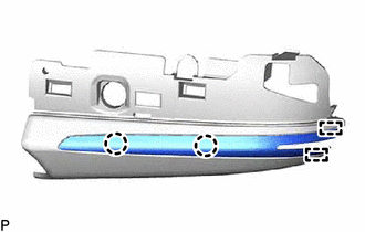
Disengage the 2 claws and 2 guides to remove the No. 2 outer mirror cover.
87945C
8.REMOVE OUTER MIRROR LOWER COVER (w/ Panoramic View Monitor System)
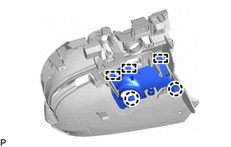
Disengage the 2 claws and 3 guides to remove the outer mirror lower cover.
81740
9.REMOVE SIDE TURN SIGNAL LIGHT ASSEMBLY
87966
10.REMOVE OUTER MIRROR RETRACTOR (w/ Power Retract Mirror)
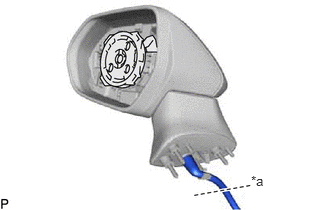
| *a | Cut Here |
Cut the wire harness sub-assembly at the position shown in the illustration.
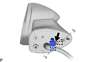
| *a | Clamp |
| *b | Guide |
Disengage the clamp.
Remove the screw.
Disengage the guide and remove the bracket.
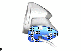
Disengage the 8 guides and remove the gasket sub-assembly.
- NOTICE:
-
Make sure to replace the gasket sub-assembly with a new one.
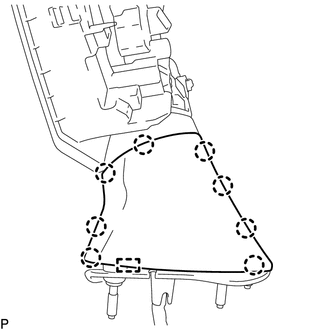
Disengage the 8 claws and guide to remove the lower cover.
- NOTICE:
-
Make sure to replace the lower cover with a new one.
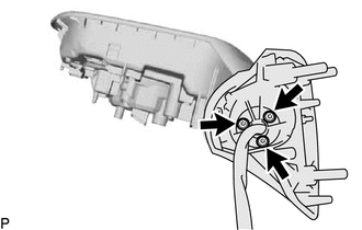
Using a T25 "TORX" socket wrench, remove the 3 screws and base sub-assembly.
- NOTICE:
-
Make sure to replace the screw with a new one.
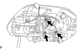
Remove the 3 screws.
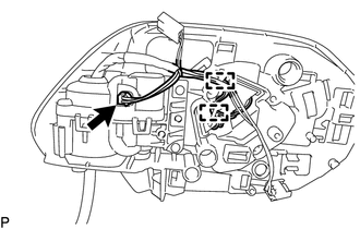
Disconnect the connector.
Disengage the 2 clamps.
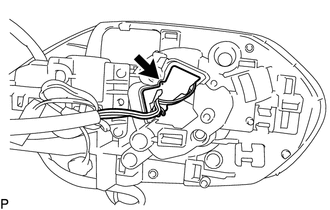
Disconnect the connector to remove the actuator sub-assembly.
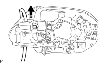

|
Remove in this Direction |
Pull the wire harness sub-assembly through the frame sub-assembly as shown in the illustration to remove the wire harness sub-assembly.
- NOTICE:
-
Make sure to replace the wire harness sub-assembly with a new one.
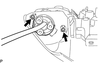
Remove the 2 screws.
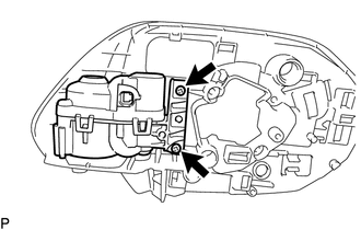
Remove the 2 screws and frame sub-assembly from the housing.
- NOTICE:
-
Make sure to replace the frame sub-assembly with a new one.