Home › Audio / Visual / Telematics › AUDIO / VIDEO › AUDIO AND VISUAL SYSTEM (for Radio Receiver Type) › 2018.04–2021.02
RM33A0E _56 Audio / Visual / Telematics _065373 AUDIO / VIDEO _0351788 AUDIO AND VISUAL SYSTEM(for Radio Receiver Type) J

AUDIO / VIDEO  AUDIO AND VISUAL SYSTEM(for Radio Receiver Type)  Speaker Circuit  


DESCRIPTION

The sound signals amplified by the radio receiver assembly are sent to the speakers from the radio receiver assembly via the speaker circuit.

If there is a short in a speaker circuit, the radio receiver assembly detects it and stops output to the speakers.

Thus sound cannot be heard from the speakers even if there is no malfunction in the radio receiver assembly, telematics transceiver or speakers.

If a short is detected in a speaker circuit, no sound can be heard from the speakers.

WIRING DIAGRAM
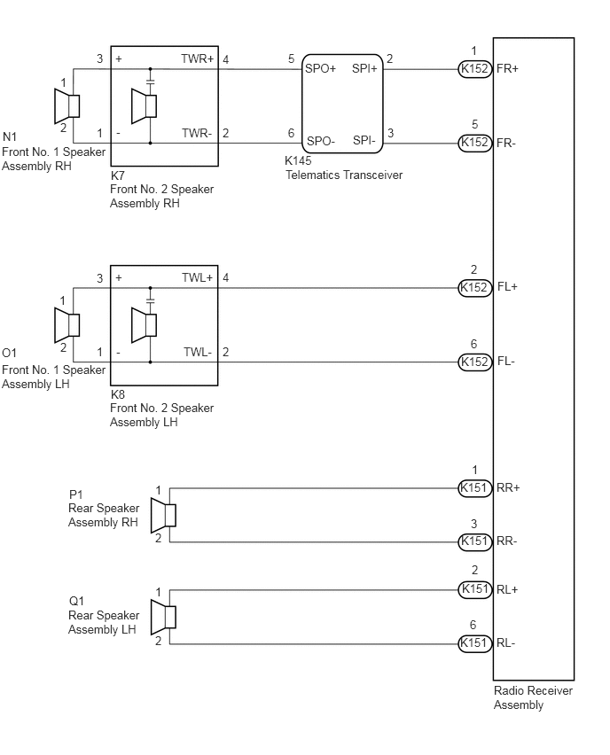
E391863E02
5.417,4.167 5.917,4.438 0.5,0.271 10 false K152 5.417,0.719 5.854,0.958 0.438,0.24 10 false K152 5.417,1.583 5.833,1.792 0.417,0.208 10 false K152 5.406,3.292 6.063,3.521 0.656,0.229 10 false K152 5.427,6.833 6.021,7.135 0.594,0.302 10 false K151 5.406,5.646 5.885,5.885 0.479,0.24 10 false K151 5.417,6.271 5.979,6.542 0.563,0.271 10 false K151 5.406,7.469 5.948,7.719 0.542,0.25 10 false K151 0.813,6.979 1.125,7.177 0.313,0.198 10 false Q1 0.813,5.729 1.125,5.927 0.313,0.198 10 false P1 1.302,4.552 1.615,4.75 0.313,0.198 10 false K8 0.021,4.063 0.479,4.26 0.458,0.198 10 false O1 1.302,1.979 1.615,2.177 0.313,0.198 10 false K7 0.021,1.698 1.302,2.677 1.281,0.979 10 false Front No. 1 Speaker Assembly RH 0.031,1.521 0.344,1.719 0.313,0.198 10 false N1 1.292,2.135 2.573,2.865 1.281,0.729 10 false Front No. 2 Speaker Assembly RH 0.021,4.26 1.313,5.052 1.292,0.792 10 false Front No. 1 Speaker Assembly LH 1.292,4.708 2.573,5.521 1.281,0.813 10 false Front No. 2 Speaker Assembly LH 1.135,1.479 1.292,1.677 0.156,0.198 10 false 1 0.708,0.885 0.865,1.083 0.156,0.198 10 false 1 5.531,0.51 5.688,0.708 0.156,0.198 10 false 1 1.135,4.052 1.292,4.25 0.156,0.198 10 false 1 0.698,3.448 0.854,3.646 0.156,0.198 10 false 1 2.615,4.052 2.771,4.25 0.156,0.198 10 false 2 0.708,1.417 0.865,1.615 0.156,0.198 10 false 2 2.615,1.479 2.771,1.677 0.156,0.198 10 false 2 4.542,0.604 4.698,0.802 0.156,0.198 10 false 2 0.708,4 0.865,4.198 0.156,0.198 10 false 2 5.531,3.083 5.688,3.281 0.156,0.198 10 false 2 1.135,3.188 1.292,3.385 0.156,0.198 10 false 3 1.135,0.604 1.292,0.802 0.156,0.198 10 false 3 4.552,1.479 4.708,1.677 0.156,0.198 10 false 3 2.615,3.177 2.771,3.375 0.156,0.198 10 false 4 2.615,0.615 2.771,0.813 0.156,0.198 10 false 4 5.542,1.375 5.698,1.573 0.156,0.198 10 false 5 3.385,0.604 3.542,0.802 0.156,0.198 10 false 5 5.531,3.958 5.688,4.156 0.156,0.198 10 false 6 3.385,1.479 3.542,1.677 0.156,0.198 10 false 6 5.833,0.719 6.292,0.917 0.458,0.198 10 false FR+ 5.833,1.594 6.292,1.792 0.458,0.198 10 false FR- 2.125,0.604 2.74,0.802 0.615,0.198 10 false TWR+ 2.135,1.479 2.75,1.677 0.615,0.198 10 false TWR- 1.354,3.177 1.51,3.375 0.156,0.198 10 false + 1.354,0.604 1.51,0.802 0.156,0.198 10 false + 1.365,4.052 1.521,4.25 0.156,0.198 10 false - 1.365,1.469 1.521,1.667 0.156,0.198 10 false - 2.135,3.177 2.75,3.375 0.615,0.198 10 false TWL+ 2.156,4.052 2.771,4.25 0.615,0.198 10 false TWL- 5.844,3.281 6.302,3.479 0.458,0.198 10 false FL+ 5.844,4.156 6.302,4.354 0.458,0.198 10 false FL- 3.583,0.719 4.198,0.917 0.615,0.198 10 false SPO+ 3.604,1.573 4.219,1.771 0.615,0.198 10 false SPO- 4.146,1.563 4.76,1.76 0.615,0.198 10 false SPI- 4.135,0.719 4.75,0.917 0.615,0.198 10 false SPI+ 3.344,1.802 3.958,2 0.615,0.198 10 false K145 3.354,1.969 6.719,2.167 3.365,0.198 10 false Telematics Transceiver 5.833,5.646 6.292,5.844 0.458,0.198 10 false RR+ 5.833,6.271 6.292,6.469 0.458,0.198 10 false RR- 5.833,6.844 6.292,7.042 0.458,0.198 10 false RL+ 5.833,7.469 6.292,7.667 0.458,0.198 10 false RL- 5.542,5.438 5.698,5.635 0.156,0.198 10 false 1 5.531,6.073 5.688,6.271 0.156,0.198 10 false 3 5.542,6.615 5.698,6.813 0.156,0.198 10 false 2 5.521,7.26 5.677,7.458 0.156,0.198 10 false 6 1.823,5.677 1.979,5.875 0.156,0.198 10 false 1 1.823,6.875 1.979,7.073 0.156,0.198 10 false 1 1.823,6.24 1.979,6.438 0.156,0.198 10 false 2 1.823,7.448 1.979,7.646 0.156,0.198 10 false 2 0.802,7.146 1.688,7.802 0.885,0.656 10 false Rear Speaker Assembly LH 0.802,5.885 1.698,6.583 0.896,0.698 10 false Rear Speaker Assembly RH 5.802,8.031 6.76,8.573 0.958,0.542 10 false Radio Receiver Assembly

PROCEDURE

1.CHECK HARNESS AND CONNECTOR (RADIO RECEIVER ASSEMBLY- TELEMATICS TRANSCEIVER - SPEAKERS)
a.

Disconnect the K152 and K151 radio receiver assembly connectors.


b.

Disconnect the K145 telematics transceiver connector.


c.

Disconnect the O1 and N1 front No. 1 speaker assembly connectors.


d.

Disconnect the K8 and K7 front No. 2 speaker assembly connectors.


e.

Disconnect the Q1 and P1 rear speaker assembly connectors.


f.

Measure the resistance according to the value(s) in the table below.

Standard Resistance:
Tester Connection Condition Specified Condition
K152-1 (FR+) - K145-2 (SPI+) Always Below 1 Ω
K152-5 (FR-) - K145-3 (SPI-) Always Below 1 Ω
K145-5 (SPO+) - K7-4 (TWR+) Always Below 1 Ω
K145-6 (SPO-) - K7-2 (TWR-) Always Below 1 Ω
K152-2 (FL+) - K8-4 (TWL+) Always Below 1 Ω
K152-6 (FL-) - K8-2 (TWL-) Always Below 1 Ω
K8-3 (+) - O1-1 Always Below 1 Ω
K8-1 (-) - O1-2 Always Below 1 Ω
K7-3 (+) - N1-1 Always Below 1 Ω
K7-1 (-) - N1-2 Always Below 1 Ω
K151-1 (RR+) - P1-1 Always Below 1 Ω
K151-3 (RR-) - P1-2 Always Below 1 Ω
K151-2 (RL+) - Q1-1 Always Below 1 Ω
K151-6 (RL-) - Q1-2 Always Below 1 Ω
K152-1 (FR+) or K145-2 (SPI+) - Body ground Always 10 kΩ or higher
K152-5 (FR-) or K145-3 (SPI-) - Body ground Always 10 kΩ or higher
K145-5 (SPO+) or K7-4 (TWR+) - Body ground Always 10 kΩ or higher
K145-6 (SPO-) or K7-2 (TWR-) - Body ground Always 10 kΩ or higher
K152-2 (FL+) or K8-4 (TWL+) - Body ground Always 10 kΩ or higher
K152-6 (FL-) or K8-2 (TWL-) - Body ground Always 10 kΩ or higher
K8-3 (+) or O1-1 - Body ground Always 10 kΩ or higher
K8-1 (-) or O1-2 - Body ground Always 10 kΩ or higher
K7-3 (+) or N1-1 - Body ground Always 10 kΩ or higher
K7-1 (-) or N1-2 - Body ground Always 10 kΩ or higher
K151-1 (RR+) or P1-1 - Body ground Always 10 kΩ or higher
K151-3 (RR-) or P1-2 - Body ground Always 10 kΩ or higher
K151-2 (RL+) or Q1-1 -Body ground Always 10 kΩ or higher
K151-6 (RL-) or Q1-2 -Body ground Always 10 kΩ or higher


Result:
Proceed to
OK
NG


OK

2.INSPECT TELEMATICS TRANSCEIVER

NG

REPAIR OR REPLACE HARNESS OR CONNECTOR

2.INSPECT TELEMATICS TRANSCEIVER
a.

Remove the telematics transceiver.

Click hereAudio / Visual / Telematics>TELEMATICS>TELEMATICS TRANSCEIVER>REMOVAL
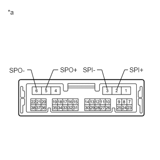

b.
E169849C05
2.51,1.917 2.677,1.5 2.677,1.5 2.75,1.5 false 2.302,1.906 2.188,1.5 2.188,1.5 2.083,1.5 false 0.781,1.906 0.667,1.5 0.667,1.5 0.583,1.5 false 0.979,1.917 1.146,1.5 1.146,1.5 1.25,1.5 false 2.781,1.417 3.146,1.635 0.365,0.219 10 false SPI+ 1.781,1.417 2.156,1.583 0.375,0.167 10 false SPI- 1.292,1.417 1.781,1.583 0.49,0.167 10 false SPO+ 0.198,1.427 0.667,1.646 0.469,0.219 10 false SPO- 0.167,0.177 0.448,0.417 0.281,0.24 10 false *a
*a Component without harness connected
(Telematics Transceiver)


Measure the resistance according to the value(s) in the table below.

Standard Resistance:
Tester Connection Condition Specified Condition
2 (SPI+) - 5 (SPO+) Always Below 1 Ω
3 (SPI-) - 6 (SPO-) Always Below 1 Ω
2 (SPI+) - 3 (SPI-) Always 10 kΩ or higher
5 (SPO+) - 6 (SPO-) Always 10 kΩ or higher
2 (SPI+) or 5 (SPO+) - Body ground Always 10 kΩ or higher
3 (SPI-) or 6 (SPO-) - Body ground Always 10 kΩ or higher


Result:
Proceed to
OK
NG


OK

3.INSPECT FRONT NO. 1 SPEAKER ASSEMBLY

NG

3.INSPECT FRONT NO. 1 SPEAKER ASSEMBLY
a.

Remove the front No. 1 speaker assembly.

Click hereAudio / Visual / Telematics>AUDIO / VIDEO>FRONT DOOR SPEAKER>REMOVAL


b.

Inspect the front No. 1 speaker assembly.

Click hereAudio / Visual / Telematics>AUDIO / VIDEO>FRONT DOOR SPEAKER>INSPECTION


Result:
Proceed to
OK
NG


OK

4.INSPECT REAR SPEAKER ASSEMBLY

NG

REPLACE FRONT NO. 1 SPEAKER ASSEMBLY

4.INSPECT REAR SPEAKER ASSEMBLY
a.

Remove the rear speaker assembly.

Click hereAudio / Visual / Telematics>AUDIO / VIDEO>REAR DOOR SPEAKER>REMOVAL


b.

Inspect the rear speaker assembly.

Click hereAudio / Visual / Telematics>AUDIO / VIDEO>REAR DOOR SPEAKER>INSPECTION


Result:
Proceed to
OK
NG


OK

5.INSPECT FRONT NO. 2 SPEAKER ASSEMBLY

NG

5.INSPECT FRONT NO. 2 SPEAKER ASSEMBLY
a.

Remove the front No. 2 speaker assembly.

Click hereAudio / Visual / Telematics>AUDIO / VIDEO>INSTRUMENT PANEL SPEAKER>REMOVAL


b.

Inspect the front No. 2 speaker assembly.

Click hereAudio / Visual / Telematics>AUDIO / VIDEO>INSTRUMENT PANEL SPEAKER>INSPECTION


Result:
Proceed to
OK
NG


OK

END (FRONT NO. 2 SPEAKER ASSEMBLY WAS DEFECTIVE)

NG