SUPPLEMENTAL RESTRAINT SYSTEMS STEERING PAD INSTALLATION
PROCEDURE

 45130
1.INSTALL HORN BUTTON ASSEMBLY
Check that the ignition switch is off.
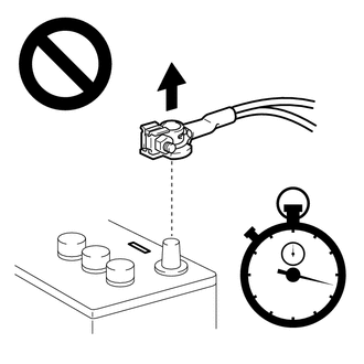
Check that the cable is disconnected from the negative (-) battery terminal.
- CAUTION:
-
-
Wait at least 90 seconds after disconnecting the cable from the negative (-) battery terminal to disable the SRS system.
w/o Occupant Classification System:
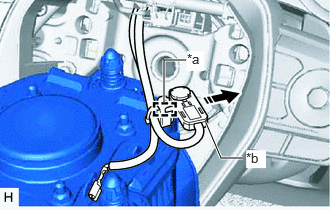
| *a | Wire Harness Clamp |
| *b | Airbag Connector |

|
Remove in this Direction |
When using a new spiral cable sub-assembly:
Engage the wire harness clamp and disconnect the airbag connector as shown in the illustration.
- HINT:
-
Be sure to engage the wire harness clamp until it is locked.
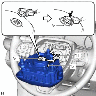
| *a | Airbag Connector |
| *b | Horn Connector |
| *c | Airbag Connector Locking Button |
| *d | Wire Harness Clamp |
|
|
Push in this Direction |
When reusing a spiral cable sub-assembly or spiral cable with sensor sub-assembly:
Engage the wire harness clamp.
- HINT:
-
Be sure to engage the wire harness clamp until it is locked.
Connect the airbag connector to the horn button assembly.
- NOTICE:
-
When connecting any airbag connector, take care not to damage the airbag wire harness.
Push in the airbag connector locking button as shown in the illustration to install the airbag connector.
Connect the horn connector to the horn button assembly.
w/ Occupant Classification System:
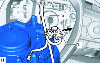
| *a | Wire Harness Clamp |
| *b | Airbag Connector |
|
|
Remove in this Direction |
When using a new spiral cable sub-assembly:
Engage the wire harness clamp and disconnect the airbag connector as shown in the illustration.
- HINT:
-
Be sure to engage the wire harness clamp until it is locked.
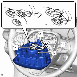
| *a | Airbag Connector |
| *b | Horn Connector |
| *c | Airbag Connector Locking Button |
| *d | Wire Harness Clamp |
|
|
Push in this Direction |
When reusing a spiral cable sub-assembly or spiral cable with sensor sub-assembly:
Engage the wire harness clamp.
- HINT:
-
Be sure to engage the wire harness clamp until it is locked.
Connect the 2 airbag connectors to the horn button assembly.
- NOTICE:
- ·
When connecting any airbag connector, take care not to damage the airbag wire harness.
·Be sure to connect the connectors to each corresponding color.
Push in the 2 airbag connector locking buttons as shown in the illustration to install the 2 airbag connectors.
Connect the horn connector to the horn button assembly.
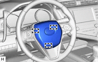
Push the horn button assembly to engage the 3 pins carefully and install the horn button assembly.
- NOTICE:
- ·
Make sure that the pins are securely inserted into the steering wheel assembly holes.
·Make sure to engage the 2 upper pins first.
·Make sure that the horn button assembly is securely installed.
45186
2.INSTALL LOWER NO. 2 STEERING WHEEL COVER
Engage each claw to install the 3 lower No. 2 steering wheel covers.
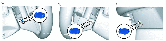
| *A | for LH Side | *B | for RH Side |
| *C | for Under Side | - | - |
3.CONNECT CABLE TO NEGATIVE BATTERY TERMINAL
for 6AR-FSE: Click hereGeneral>MAINTENANCE>6AR-FSE BATTERY>INSTALLATION
for 2AR-FE: Click hereGeneral>MAINTENANCE>2AR-FE BATTERY>INSTALLATION
for A25A-FKS: Click hereGeneral>MAINTENANCE>A25A-FKS BATTERY>INSTALLATION
for 2GR-FKS: Click hereGeneral>MAINTENANCE>2GR-FKS BATTERY>INSTALLATION
- NOTICE:
-
When disconnecting the cable, some systems need to be initialized after the cable is reconnected.
-
Click hereGeneral>INTRODUCTION>REPAIR INSTRUCTION>INITIALIZATION
45130
4.INSPECT HORN BUTTON ASSEMBLY
Make sure that the horn sounds.
If the horn does not sound, inspect the horn system.
Click hereVehicle Exterior>HORN>HORN SYSTEM>PROBLEM SYMPTOMS TABLE
5. PERFORM DIAGNOSTIC SYSTEM CHECK
6.INSPECT SRS WARNING LIGHT