DOOR / HATCH FUEL LID OPENER SYSTEM TERMINALS OF ECU
CHECK INSTRUMENT PANEL JUNCTION BLOCK ASSEMBLY AND MAIN BODY ECU (MULTIPLEX NETWORK BODY ECU) (for TMC Made)
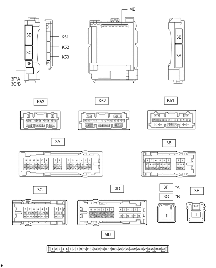
| *A | for LHD | *B | for RHD |
Remove the main body ECU (multiplex network body ECU) from the instrument panel junction block assembly.
Click herePower Source / Network>POWER DISTRIBUTION>MAIN BODY ECU>REMOVAL
Reconnect the instrument panel junction block assembly connectors.
Measure the resistance and voltage according to the value(s) in the table below.
- HINT:
-
Measure the values on the wire harness side with the connectors disconnected.
| Terminal No. (Symbol) | Wiring Color | Terminal Description | Condition | Specified Condition |
|---|---|---|---|---|
| MB-11 (GND1) - Body ground | - | Ground | Always | Below 1 Ω |
| MB-31 (BECU) - Body ground | - | Battery power supply | Always | 11 to 14 V |
| MB-30 (ACC) - Body ground | - | ACC power supply | Ignition switch ACC | 11 to 14 V |
| MB-30 (ACC) - Body ground | - | ACC power supply | Ignition switch off | Below 1 V |
| MB-32 (IG) - Body ground | - | IG power supply | Ignition switch ON | 11 to 14 V |
| MB-32 (IG) - Body ground | - | IG power supply | Ignition switch off | Below 1 V |
Install the main body ECU (multiplex network body ECU) to the instrument panel junction block assembly.
Click herePower Source / Network>POWER DISTRIBUTION>MAIN BODY ECU>INSTALLATION
Measure the voltage and check for pulses according to the value(s) in the table below.
| Terminal No. (Symbol) | Wiring Color | Terminal Description | Condition | Specified Condition |
|---|---|---|---|---|
| K52-15 (FUSW) - Body ground | G - Body ground | Fuel lid opener switch signal | Fuel lid opener switch pushed | Below 1 V |
| Fuel lid opener switch not pushed | 11 to 14 V | |||
| K51-24 (FUEL) - Body ground | G - Body ground | Fuel lid open request signal | 1.
Ignition switch off 2.
Fuel lid opener switch not pushed → pushed for 0.8 second |
11 to 14 V → Below 1 V → 11 to 14 V |