M20A-FKS ENGINE CONTROL ACTIVE CONTROL ENGINE MOUNT(for Front Side) REMOVAL
CAUTION / NOTICE / HINT
The necessary procedures (adjustment, calibration, initialization or registration) that must be performed after parts are removed and installed, or replaced during front engine mounting insulator removal/installation are shown below.
| Replaced Part or Performed Procedure | Necessary Procedure | Effect/Inoperative Function when Necessary Procedure not Performed | Link |
|---|---|---|---|
| Battery terminal is disconnected/reconnected | Perform steering sensor zero point calibration | Lane Tracing Assist System | ( ) |
| Pre-collision System | |||
| Memorize steering angle neutral point | Parking Assist Monitor System | ()
|
|
| Panoramic View Monitor System | ()
|
- NOTICE:
-
After turning the ignition switch off, waiting time may be required before disconnecting the cable from the negative (-) battery terminal. Therefore, make sure to read the disconnecting the cable from the negative (-) battery terminal notices before proceeding with work.
-
Click hereGeneral>INTRODUCTION>REPAIR INSTRUCTION>PRECAUTION
PROCEDURE

 1.DISCONNECT CABLE FROM NEGATIVE BATTERY TERMINAL
2.DRAIN ENGINE COOLANT
53295E
3.REMOVE COOL AIR INTAKE DUCT SEAL
12601B
4.REMOVE NO. 1 ENGINE COVER SUB-ASSEMBLY
17750A
5.REMOVE INLET AIR CLEANER ASSEMBLY
6.REMOVE AIR CLEANER ASSEMBLY WITH AIR CLEANER HOSE
17650H
7.REMOVE VACUUM SWITCHING VALVE (for Active Control Engine Mount System)
16571C
8.DISCONNECT NO. 1 RADIATOR HOSE
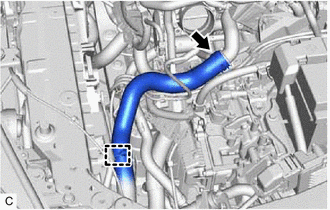
Disengage the clamp and disconnect the No. 1 radiator hose from the fan with motor assembly.
Slide the clip and disconnect the No. 1 radiator hose from the water outlet.
16261G
9.DISCONNECT NO. 1 WATER BY-PASS HOSE
Click hereDrivetrain>K120 (CVT)>OIL COOLER>REMOVAL
82121
10.DISCONNECT ENGINE WIRE
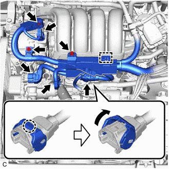
Open the terminal cap.
Remove the nut and 2 bolts.
Disconnect the generator assembly connector, sensor wire connector and engine water pump assembly (water inlet housing) connector.
Disengage the claw and raise the lock lever to disconnect the No. 6 engine wire connector as shown in the illustration.
Disengage the clamp.
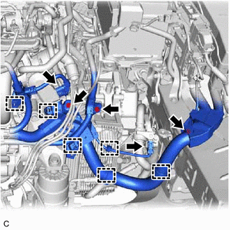
Remove the 3 bolts.
Disconnect the flow shutting valve (water valve) connector and throttle body with motor assembly connector.
Disengage the 6 clamps.
12361A
11.REMOVE FRONT ENGINE MOUNTING INSULATOR
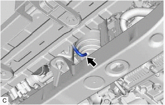
Disconnect the vacuum hose from the front engine mounting insulator.
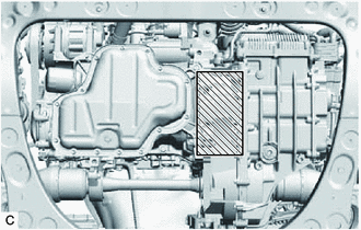

|
Wooden Block Placement Location |
Support the engine assembly with transaxle using a jack and wooden block.
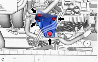
Remove the 4 bolts and front engine mounting bracket.
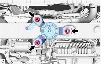
Remove the 3 nuts and front engine mounting insulator from the front frame assembly.