DRIVE SHAFT / PROPELLER SHAFT FRONT DRIVE SHAFT ASSEMBLY(for A25A-FKS) REMOVAL
CAUTION / NOTICE / HINT
The necessary procedures (adjustment, calibration, initialization, or registration) that must be performed after parts are removed and installed, or replaced during front drive shaft assembly removal/installation are shown below.
| Replaced Part or Performed Procedure | Necessary Procedure | Effect/Inoperative Function when Necessary Procedure not Performed | Link |
|---|---|---|---|
| Front wheel alignment adjustment | ·
Perform "Reset Memory" ·
Perform acceleration sensor zero point calibration and system information memorization |
·
VSC disabled or malfunctioning ·
DTCs are output ·
Slip indicator light illuminated ·
ABS warning light illuminated |
( ) |
| Replacement of automatic transaxle fluid | ATF thermal degradation estimate reset | The value of the Data List item "ATF Thermal Degradation Estimate" is not estimated correctly. | ()
|
- HINT:
- ·
Use the same procedure for the RH side and LH side.
·The following procedure is for the LH side.
PROCEDURE

 1.REMOVE FRONT WHEELS
53851M
2.REMOVE FRONT WHEEL OPENING EXTENSION PAD RH
53852K
3.REMOVE FRONT WHEEL OPENING EXTENSION PAD LH
51441
4.REMOVE NO. 1 ENGINE UNDER COVER (w/ No. 2 Engine Under Cover)
5.REMOVE NO. 2 ENGINE UNDER COVER ASSEMBLY (w/ No. 2 Engine Under Cover)
53737B
6.REMOVE FRONT FENDER APRON SEAL LH
53736
7.REMOVE FRONT FENDER APRON SEAL RH
8.DRAIN AUTOMATIC TRANSAXLE FLUID
43502H
9.REMOVE FRONT AXLE SHAFT NUT
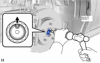
Using SST and a hammer, release the staked part of the front axle shaft nut.
- SST
- 09930-00010
- NOTICE:
-
Fully loosen the staked part of the front axle shaft nut, otherwise the threads of the drive shaft may be damaged.
While applying the brakes, remove the front axle shaft nut.
89543
10.SEPARATE FRONT SPEED SENSOR
45470
11.SEPARATE TIE ROD ASSEMBLY
48810
12.SEPARATE FRONT STABILIZER LINK ASSEMBLY
48069
13.SEPARATE FRONT LOWER NO. 1 SUSPENSION ARM SUB-ASSEMBLY
14.SEPARATE FRONT DRIVE SHAFT ASSEMBLY
43420
15.REMOVE FRONT DRIVE SHAFT ASSEMBLY LH
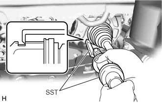
Using SST, remove the front drive shaft assembly LH.
- SST
- 09520-01010
09520-24010 (09520-32040)
- NOTICE:
- ·
Do not damage the front drive shaft oil seal LH.
·Do not damage the front axle inboard joint boot.
·Do not drop the front drive shaft assembly LH.
43410
16.REMOVE FRONT DRIVE SHAFT ASSEMBLY RH
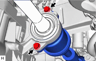
Remove the 2 bolts and pull out the drive shaft together with the drive shaft bearing case sub-assembly.
Remove the front drive shaft assembly RH from the drive shaft bearing bracket.
- NOTICE:
- ·
Do not damage the front drive shaft oil seal RH.
·Do not damage the front axle inboard joint boot.
·Do not drop the front drive shaft assembly RH.
- HINT:
-
If it is difficult to disengage the fitting, lightly tap the end of the front drive inboard joint assembly using a brass bar and a hammer.
43420G
17.REMOVE FRONT DRIVE SHAFT HOLE SNAP RING
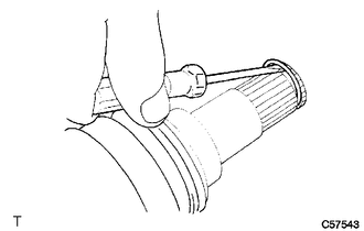
Using a screwdriver, remove the front drive shaft hole snap ring.