A25A-FKS ENGINE CONTROL ACTIVE CONTROL ENGINE MOUNT(for Front Side) INSTALLATION
PROCEDURE

 12361A
1.INSTALL FRONT ENGINE MOUNTING INSULATOR
Install the stay to the front engine mounting insulator with the nut.
- Torque:
- 6.0 N*m (61 kgf*cm, 53 in.*lbf)
Install the front engine mounting insulator to the front frame assembly with the 3 nuts.
- Torque:
- 72 N*m (734 kgf*cm, 53 ft.*lbf)
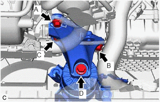
Install the front engine mounting bracket to the transaxle housing with the 3 bolts.
- Torque:
- Bolt (A), (B) and (C) : 42 N*m (428 kgf*cm, 31 ft.*lbf)
- NOTICE:
-
Temporarily tighten the bolt (A), and then fully tighten the 3 bolts in the order of (B), (C) and (A).
Install the front engine mounting bracket to the front engine mounting insulator with the bolt.
- Torque:
- Bolt (D) : 72 N*m (734 kgf*cm, 53 ft.*lbf)
Connect the vacuum hose to the front engine mounting insulator.
Engage the 2 clamps to install the vacuum hoses to the front engine mounting insulator.
Install the No. 1 radiator bracket to the front engine mounting bracket with the bolt.
- Torque:
- 19 N*m (194 kgf*cm, 14 ft.*lbf)
Engage the 4 clamps to install the radiator hose, vacuum hoses and No. 2 engine wire to the No. 1 radiator bracket.
2.INSTALL NO. 2 ENGINE UNDER COVER ASSEMBLY (w/ Cover)
51441
3.INSTALL NO. 1 ENGINE UNDER COVER
53852K
4.INSTALL FRONT WHEEL OPENING EXTENSION PAD LH
53851M
5.INSTALL FRONT WHEEL OPENING EXTENSION PAD RH
17650H
6.INSTALL VACUUM SWITCHING VALVE (for Active Control Engine Mount System)