P710 HYBRID TRANSMISSION / TRANSAXLE MOTOR CABLE REMOVAL
CAUTION / NOTICE / HINT
The necessary procedures (adjustment, calibration, initialization, or registration) that must be performed after parts are removed and installed, or replaced during motor cable removal/installation are shown below.
| Replaced Part or Performed Procedure | Necessary Procedure | Effect/Inoperative Function when Necessary Procedure not Performed | Link |
|---|---|---|---|
| Auxiliary battery terminal is disconnected/reconnected | Perform steering sensor zero point calibration | Lane departure alert system (w/ steering control) | ( ) |
| Pre-collision system | |||
| Memorize steering angle neutral point | Parking assist monitor system | ()
|
|
| Replacement of ECM | Vehicle Identification Number (VIN) or frame number registration | MIL illuminates | ()(w/ Canister Pump Module)
( )(w/o Canister Pump Module)
|
| Replacement of inverter with converter assembly | Resolver learning | ·
DTCs are stored ·
Slight vibration at a vehicle speed of 5 km/h (3 mph) or less ·
Shock or vibration during acceleration |
()
|
- CAUTION:
- ·
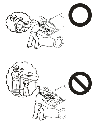
Orange wire harnesses and connectors indicate high-voltage circuits. To prevent electric shock, always follow the procedure described in the repair manual.
·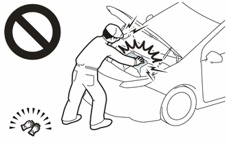
To prevent electric shock, wear insulated gloves when working on wire harnesses and components of the high voltage system.
- NOTICE:
- ·
After turning the power switch off, waiting time may be required before disconnecting the cable from the negative (-) auxiliary battery terminal. Therefore, make sure to read the disconnecting the cable from the negative (-) auxiliary battery terminal notices before proceeding with work.
Click hereGeneral>INTRODUCTION>REPAIR INSTRUCTION>PRECAUTION
·If the ECM has been struck or dropped, replace it.
·Perform Vehicle Identification Number (VIN) registration when replacing the ECM.
w/ Canister Pump Module: Click hereEngine / Hybrid System>A25A-FXS (ENGINE CONTROL)>SFI SYSTEM (w/ Canister Pump Module)>REGISTRATION
w/o Canister Pump Module: Click hereEngine / Hybrid System>A25A-FXS (ENGINE CONTROL)>SFI SYSTEM (w/o Canister Pump Module)>REGISTRATION
PROCEDURE

 G9200
1.REMOVE INVERTER WITH CONVERTER ASSEMBLY
G1148
2.REMOVE MOTOR CABLE
- CAUTION:
-
Be sure to wear insulated gloves.
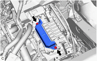
Remove the 2 bolts and connector cover from the hybrid vehicle transaxle assembly.
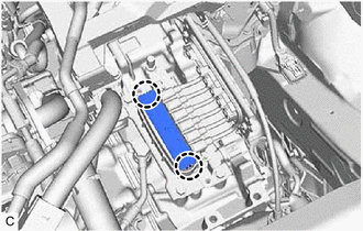
Disengage the 2 claws to remove the terminal cap from the hybrid vehicle transaxle assembly.
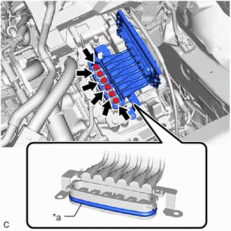
| *a | Waterproof Seal |
Using an insulated tool, remove the 6 bolts and motor cable from the hybrid vehicle transaxle assembly.
- NOTICE:
- ·
Keep the motor cable terminals and their installation area free from foreign matter, water, etc.
·Do not touch the waterproof seal or terminals of the motor cable.
·Cover the hole where the motor cable was installed with tape or equivalent (non-residue type) to prevent entry of foreign matter.