A25A-FXS COOLING RADIATOR ON-VEHICLE INSPECTION
CAUTION / NOTICE / HINT
- CAUTION:
-
-
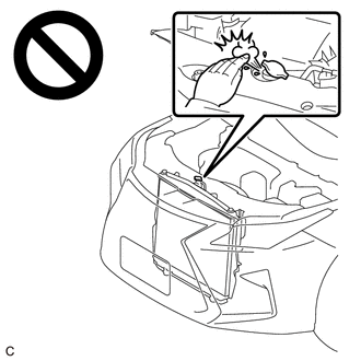
Do not remove the radiator cap sub-assembly while the engine and radiator assembly are still hot. Pressurized, hot engine coolant and steam may be released and cause serious burns.
PROCEDURE

 16401
1.CHECK RADIATOR CAP SUB-ASSEMBLY
- CAUTION:
-
Do not remove the radiator cap sub-assembly while the engine and radiator assembly are still hot. Pressurized, hot engine coolant and steam may be released and cause serious burns.
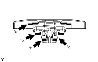
| *a | Rubber Packing (1) |
| *b | Rubber Packing (2) |
| *c | Rubber Packing (3) |
| *d | Valve Seat |
Measure the valve opening pressure.
If there are water stains or foreign matter on the rubber packing (1), (2) or (3), clean the part(s) with water and finger scouring.
Check that the rubber packings (1), (2) and (3) are not deformed, cracked or swollen.
Check that the rubber packing (3) and valve seat are not stuck together.
Apply engine coolant to the rubber packings (2) and (3) before using a radiator cap tester.
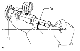
| *1 | Radiator Cap Sub-assembly |
| *a | Radiator Cap Tester |
| *b | 30° or more |
When using the radiator cap tester, tilt it upward 30° or more.
Pump the radiator cap tester several times, and check the maximum pressure.
- Pumping Speed:
1 pump per second
- HINT:
-
Even if the radiator cap sub-assembly cannot maintain the maximum pressure, it is not a defect.
- Result:
Item Specified Condition Standard pressure
(for brand-new radiator cap sub-assembly)74 to 103 kPa (0.8 to 1.1 kgf/cm2, 10.7 to 14.9 psi) Minimum pressure
(for used radiator cap sub-assembly)59 kPa (0.6 kgf/cm2, 8.6 psi)
If the maximum pressure is less than the minimum pressure, replace the radiator cap sub-assembly.
2.CHECK RADIATOR ASSEMBLY FOR CLOGGING
- CAUTION:
-
To prevent burns, do not touch the engine or other high temperature components while the engine is hot.
Remove the cool air intake duct seal.
Click hereVehicle Exterior>EXTERIOR PANELS / TRIM>FRONT BUMPER>REMOVAL
Remove the inlet air cleaner assembly.
Click hereEngine / Hybrid System>HYBRID / BATTERY CONTROL>INVERTER WITH CONVERTER>REMOVAL
Shine an electric light at the radiator assembly and cooler condenser assembly from the front of the cooler condenser assembly and check the radiator assembly for clogging using a mirror.
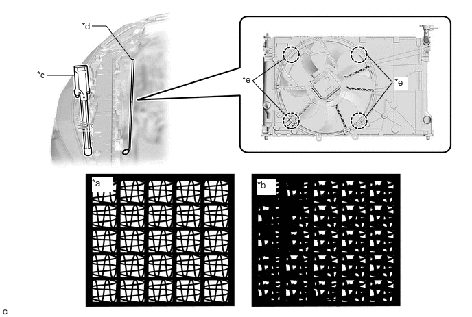
| *a | OK | *b | NG |
| *c | Electric Light | *d | Mirror |
| *e | Areas to be checked | - | - |
- OK:
The radiator assembly is not clogged.
If the radiator assembly is clogged, clean it.
Install the inlet air cleaner assembly.
Click hereEngine / Hybrid System>HYBRID / BATTERY CONTROL>INVERTER WITH CONVERTER>INSTALLATION
Install the cool air intake duct seal.
Click hereVehicle Exterior>EXTERIOR PANELS / TRIM>FRONT BUMPER>INSTALLATION
3.CLEAN RADIATOR ASSEMBLY
- CAUTION:
-
To prevent burns, do not touch the engine or other high temperature components while the engine is hot.
Remove the cool air intake duct seal.
Click hereVehicle Exterior>EXTERIOR PANELS / TRIM>FRONT BUMPER>REMOVAL
Remove the inlet air cleaner assembly.
Click hereEngine / Hybrid System>HYBRID / BATTERY CONTROL>INVERTER WITH CONVERTER>REMOVAL
Cover the opening of each air duct with a piece of cloth.
Clean the cooler condenser assembly.
Check that the washer nozzle is not clogged.
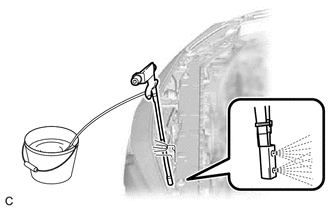
Insert the washer nozzle into the space in front of the cooler condenser assembly and spray it.
- NOTICE:
- ·
Clean the fins of the cooler condenser assembly by spraying the entire area for 150 seconds. Repeat this process twice.
·Set the air pressure to 0.4 MPa (4.1 kgf/cm2, 58 psi).
·Check that water sprays in mist form from the nozzle.
·Keep the nozzle parallel to the cooler condenser assembly.
·Do not allow the nozzle to contact the fins of the cooler condenser assembly.
·Keep the nozzle moving while spraying water.
·Do not spray the cooler compressor assembly or generator assembly excessively.
Leave the cooler condenser assembly as is for 10 minutes to let the water penetrate the dirt.
Clean the cooler condenser assembly again.
- NOTICE:
- ·
Clean the fins of the cooler condenser assembly by spraying the entire area for 150 seconds. Repeat this process 4 times.
·Set the air pressure to 0.4 MPa (4.1 kgf/cm2, 58 psi).
·Check that water sprays in mist form from the nozzle.
·Keep the nozzle parallel to the cooler condenser assembly.
·Do not allow the nozzle to contact the fins of the cooler condenser assembly.
·Keep the nozzle moving while spraying water.
·Do not spray the cooler compressor assembly or generator assembly excessively.
Using an air blow gun, dry the cooler condenser assembly for 3 minutes.
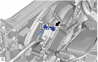
Disconnect the cooling fan motor connector.
Disengage the wire harness clamp.
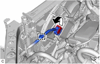
Rotate the lever while pushing the lock, and disconnect the cooling fan motor connector.
- NOTICE:
-
After disconnecting the cooling fan motor connector, make sure that dirt, water or other foreign matter does not contact the connecting parts of the cooling fan motor connector.
Disengage the wire harness clamp.
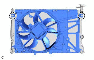
Disengage the 2 claws and separate the fan with motor assembly from the radiator assembly.
Clean the radiator assembly.
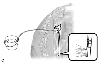
Insert the washer nozzle between the radiator assembly and fan with motor assembly and spray the radiator assembly.
- NOTICE:
- ·
Clean the fins of the radiator assembly by spraying the entire area for 150 seconds. Repeat this process twice.
·Set the air pressure to 0.4 MPa (4.1 kgf/cm2, 58 psi).
·Check that water sprays in mist form from the nozzle.
·Keep the nozzle parallel to the radiator assembly.
·Do not allow the nozzle to contact the fins of the radiator assembly.
·Keep the nozzle moving while spraying water.
Leave the radiator assembly as is for 10 minutes to let the water penetrate the dirt.
Clean the radiator assembly again.
- NOTICE:
- ·
Clean the fins of the radiator assembly by spraying the entire area for 150 seconds. Repeat this process 4 times.
·Set the air pressure to 0.4 MPa (4.1 kgf/cm2, 58 psi).
·Check that water sprays in mist form from the nozzle.
·Keep the nozzle parallel to the radiator assembly.
·Do not allow the nozzle to contact the fins of the radiator assembly.
·Keep the nozzle moving while spraying water.
Using an air blow gun, dry the radiator assembly for 3 minutes.
Check the fins of the radiator assembly for clogs again.
If the radiator assembly is clogged, clean the cooler condenser assembly and radiator assembly again.
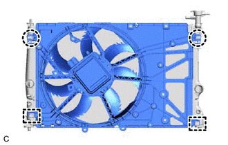
Check that the 2 guides at the bottom are engaged to the radiator assembly.
Engage the 2 claws to install the fan with motor assembly to the radiator assembly.
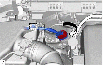
Engage the wire harness clamp.
Connect the cooling fan motor connector and rotate the lever to lock it.
- NOTICE:
- ·
When connecting the cooling fan motor connector, make sure that the connecting parts of the cooling fan motor connector are free of dirt, water or other foreign matter.
·Be sure to securely connect the cooling fan motor connector.
Engage the wire harness clamp.
Connect the cooling fan motor connector.
Remove the piece of cloth from the opening of each air duct.
Install the inlet air cleaner assembly.
Click hereEngine / Hybrid System>HYBRID / BATTERY CONTROL>INVERTER WITH CONVERTER>INSTALLATION
Install the cool air intake duct seal.
Click hereVehicle Exterior>EXTERIOR PANELS / TRIM>FRONT BUMPER>INSTALLATION