WIPER / WASHER WIPER AND WASHER SYSTEM Wiper Motor Power Source Circuit
DESCRIPTION
This circuit is the power source circuit for the windshield wiper motor assembly.
WIRING DIAGRAM
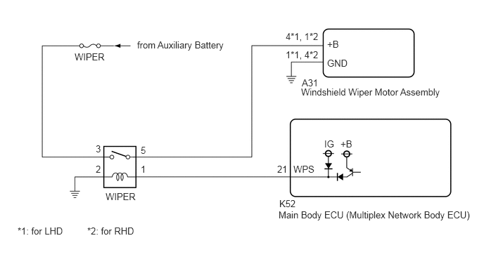
CAUTION / NOTICE / HINT
- NOTICE:
- ·
Inspect the fuses of circuits related to this system before performing the following procedure.
·Before replacing the main body ECU (multiplex network body ECU), refer to Service Bulletin.
PROCEDURE
Connect the GTS to the DLC3.
Turn the power switch on (IG).
Turn the GTS on.
Enter the following menus: Body Electrical / Wiper / Data List.
Read the Data List according to the display on the GTS.
- Body Electrical > Wiper > Data List
-
Tester Display Measurement Item Range Normal Condition Diagnostic Note Motor Power Supply Voltage Front wiper motor assembly supply voltage status Min.: 0 V
Max.: 63 VAlmost the same as actual front wiper motor assembly voltage -
- Body Electrical > Wiper > Data List
-
Tester Display Motor Power Supply Voltage - 50003 384 37
- OK:
The GTS display is normal.
- Result:
Proceed to OK NG
OK
NG
Disconnect the A31 windshield wiper motor assembly connector.
Measure the resistance according to the value(s) in the table below.
- Standard Resistance:
for LHD Tester Connection Condition Specified Condition A31-1 (GND) - Body ground Always Below 1 Ω
for RHD Tester Connection Condition Specified Condition A31-4 (GND) - Body ground Always Below 1 Ω
- Result:
Proceed to OK NG
OK
NG
Measure the voltage according to the value(s) in the table below.
- Standard Voltage:
for LHD Tester Connection Condition Specified Condition A31-4 (+B) - Body ground Power switch on (IG) 11 to 14 V Less than approximately 60 seconds after power switch turned off 11 to 14 V Approximately 60 seconds after power switch turned off Below 1 V
for RHD Tester Connection Condition Specified Condition A31-1 (+B) - Body ground Power switch on (IG) 11 to 14 V Less than approximately 60 seconds after power switch turned off 11 to 14 V Approximately 60 seconds after power switch turned off Below 1 V
- Result:
Proceed to OK NG
OK
NG
Inspect the WIPER relay.
Click hereVehicle Exterior>WIPER / WASHER>RELAY>ON-VEHICLE INSPECTION
- Result:
Proceed to OK NG
OK
NG
Measure the voltage according to the value(s) in the table below.
- Standard Voltage:
Tester Connection Condition Specified Condition 3 (WIPER relay) - Body ground Power switch off 11 to 14 V
- Result:
Proceed to OK NG
OK
NG
Measure the resistance according to the value(s) in the table below.
- Standard Resistance:
Tester Connection Condition Specified Condition 2 (WIPER relay) - Body ground Always Below 1 Ω
- Result:
Proceed to OK NG
OK
NG
Measure the resistance according to the value(s) in the table below.
- Standard Resistance:
for LHD Tester Connection Condition Specified Condition 5 (WIPER relay) - A31-4 (+B) Always 10 kΩ or higher 5 (WIPER relay) or A31-4 (+B) - Body ground Always Below 1 Ω
for RHD Tester Connection Condition Specified Condition 5 (WIPER relay) - A31-1 (+B) Always 10 kΩ or higher 5 (WIPER relay) or A31-1 (+B) - Body ground Always Below 1 Ω
- Result:
Proceed to OK NG
OK
NG
Disconnect the K52 main body ECU (multiplex network body ECU) connector.
Measure the resistance according to the value(s) in the table below.
- Standard Resistance:
Tester Connection Condition Specified Condition 1 (WIPER relay) - K52-21 (WPS) Always Below 1 Ω 1 (WIPER relay) or K52-21 (WPS) - Body ground Always 10 kΩ or higher
- Result:
Proceed to OK NG
OK
NG