AUDIO / VIDEO RADIO RECEIVER INSTALLATION
PROCEDURE

 1. PRECAUTION (w/o Navigation System)
- NOTICE:
- ·
When replacing the radio and display receiver assembly, always replace it with a new one. If a radio and display receiver assembly which was installed to another vehicle is used, the following may occur:
-A communication malfunction DTC may be stored.
-The radio and display receiver assembly may not operate normally.
2. PRECAUTION (w/ Navigation System)
- NOTICE:
- ·
When replacing the radio and display receiver assembly or navigation ECU, always replace it with a new one. If a radio and display receiver assembly or navigation ECU which was installed to another vehicle is used, the following may occur:
-A communication malfunction DTC may be stored.
-The radio and display receiver assembly or navigation ECU may not operate normally.
·After replacing the radio and display receiver assembly, if "New software is not compatible with the system. Contact your dealer." is displayed on the multi-display, update the software of the navigation ECU.
86140A
3.INSTALL RADIO AND DISPLAY RECEIVER ASSEMBLY
4.INSTALL NAVIGATION ECU WITH WIRE (w/ Navigation System)
86212C
5.INSTALL NO. 2 RADIO RECEIVER BRACKET
w/o Navigation System:
Install the No. 2 radio receiver bracket with the 3 screws.
w/ Navigation System:
Install the No. 2 radio receiver bracket with the 5 screws.
86211J
6.INSTALL NO. 1 RADIO RECEIVER BRACKET
w/o Navigation System:
Install the No. 1 radio receiver bracket with the 3 screws.
w/ Navigation System:
Install the No. 1 radio receiver bracket with the 5 screws.
7.CONNECT NAVIGATION ECU WITH WIRE (w/ Navigation System)
Connect the 2 connectors to connect the navigation ECU with wire.
86453
8.INSTALL MULTI-MEDIA MODULE WIRE (for 8 Inch Display)
Engage the claw.
Connect the connector to install the multi-media module wire.
83950M
9.INSTALL TELLTALE LIGHT ASSEMBLY (for 7 Inch Display)
10.INSTALL RADIO AND DISPLAY RECEIVER ASSEMBLY WITH BRACKET (for 7 Inch Display)
Connect each connector.
Engage the 2 guides to temporarily install the radio and display receiver assembly with bracket as shown in the illustration.
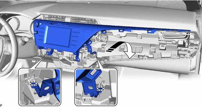

|
Install in this Direction | - | - |
Engage the 5 clips as shown in the illustration.
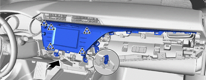
|
|
Install in this Direction | - | - |
Engage the 4 clips in the order shown in the illustration.
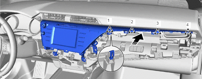
|
|
Install in this Direction | - | - |
Install the radio and display receiver assembly with bracket with the 4 bolts.
11.INSTALL RADIO AND DISPLAY RECEIVER ASSEMBLY WITH BRACKET (for 8 Inch Display)
Connect each connector.
Engage the 2 guides to temporarily install the radio and display receiver assembly with bracket as shown in the illustration.
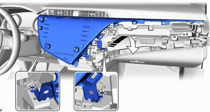
|
|
Install in this Direction | - | - |
Engage the 7 clips as shown in the illustration.
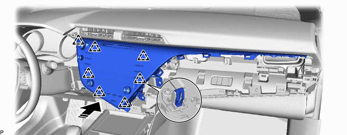
|
|
Install in this Direction | - | - |
Engage the 4 clips in the order shown in the illustration.
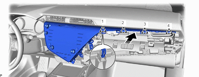
|
|
Install in this Direction | - | - |
Install the radio and display receiver assembly with bracket with the 4 bolts.
55900
12.INSTALL AIR CONDITIONING CONTROL ASSEMBLY (for 7 Inch Display)
55670
13.INSTALL NO. 3 INSTRUMENT PANEL REGISTER ASSEMBLY
55480D
14.INSTALL LOWER INSTRUMENT PANEL FINISH PANEL ASSEMBLY
55012A
15.INSTALL NO. 2 INSTRUMENT PANEL GARNISH SUB-ASSEMBLY
55435B
16.INSTALL NO. 1 METER HOOD CLUSTER
17. CUSTOMIZE POWER TILT AND POWER TELESCOPIC STEERING COLUMN SYSTEM (for Power Tilt and Power Telescopic Steering Column)