DOOR / HATCH FUEL LID OPENER SYSTEM Fuel Lid Opener does not Operate
DESCRIPTION
When the fuel lid opener switch is pushed for 0.8 seconds, a fuel lid opener switch signal is sent to the ECM via the main body ECU (multiplex network ECU). The ECM turns on the FUEL OPN relay and EFI-MAIN NO. 1 relay, and the fuel lid lock with motor assembly opens the fuel lid. When the fuel lid is open, a fuel lid courtesy switch signal is output from the fuel lid lock with motor assembly.*1
When the fuel lid opener switch is pushed for 0.8 second, the main body ECU (multiplex network ECU) turns on the FUEL OPN relay, and the fuel lid lock with motor assembly opens the fuel lid.*2
*1: w/ Canister Pump Module
*2: w/o Canister Pump Module
WIRING DIAGRAM
w/ Canister Pump Module
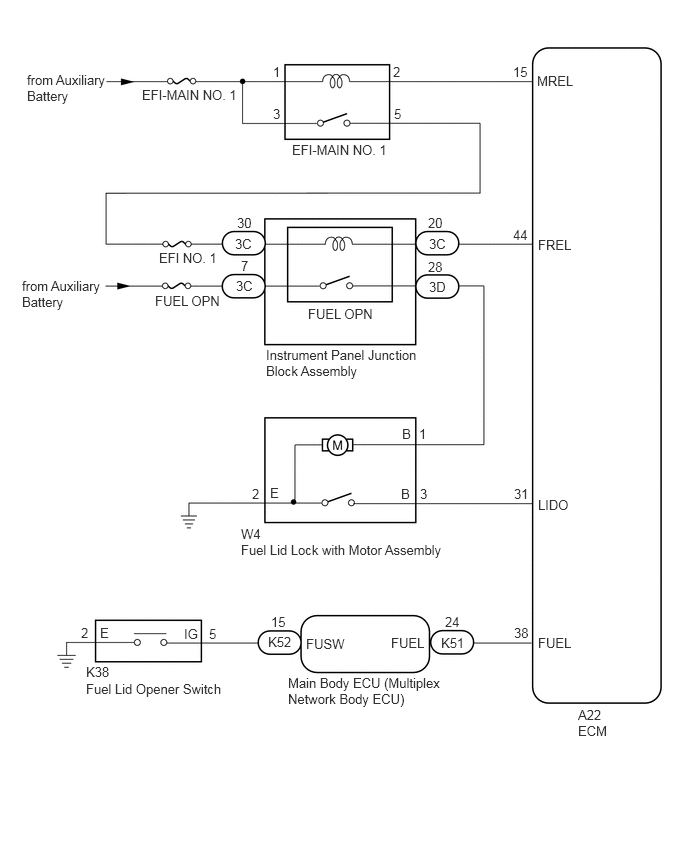
w/o Canister Pump Module
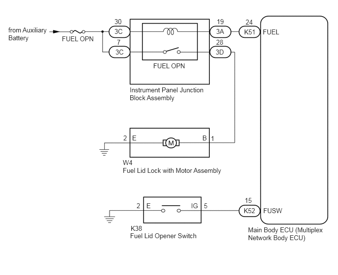
CAUTION / NOTICE / HINT
- NOTICE:
- ·
Inspect the fuses for circuits related to this system before performing the following procedure.
·Before replacing the main body ECU (multiplex network body ECU), refer to Service Bulletin.
PROCEDURE
Choose the model to be inspected.
- Result:
Result Proceed to w/ Canister Pump Module A w/o Canister Pump Module B
A
B
Connect the GTS to the DLC3.
Turn the power switch on (IG).
Turn the GTS on.
Enter the following menus: System Select / Health Check.
Check DTCs.
- Result:
Result Proceed to No DTCs are output. A DTCs are output. B
A
B
Perform the Evaporative System Check using the GTS (Automatic Mode). Refer to "CONFIRMATION DRIVING PATTERN" of P045011.
Click hereEngine / Hybrid System>A25A-FXS (ENGINE CONTROL)>SFI SYSTEM (w/ Canister Pump Module)>P045011
Check for DTCs.
- Powertrain > Engine > Trouble Codes
- 50001 372
- OK:
Evaporative emission control system DTCs are not output.
- Result:
Proceed to OK NG
OK
NG
Enter the following menus: Powertrain / Engine / Active Test.
Perform the Active Test according to the display on the GTS.
- Powertrain > Engine > Active Test
-
Tester Display Measurement Item Control Range Diagnostic Note Activate the Fuel Filler Opener Fuel lid lock with motor assembly OFF/ON -
- Powertrain > Engine > Active Test
-
Tester Display Activate the Fuel Filler Opener - 50004 372 41
- OK:
The fuel lid lock with motor assembly operates normally.
- Result:
Proceed to OK NG
OK
NG
Enter the following menus: Powertrain / Engine / Data List.
Read the Data List according to the display on the GTS.
- Powertrain > Engine > Data List
-
Tester Display Measurement Item Range Normal Condition Diagnostic Note Fuel Lid SW Fuel lid open request signal Close or Open Close: Fuel lid opener switch not pushed for 0.8 seconds.
Open: Fuel lid opener switch pushed for 0.8 seconds.·Customize settings set to default
·The Data List item "Fuel Lid SW" indicates when fuel lid request signal sent from the main body ECU (multiplex network body ECU) is received by the ECM. The fuel lid takes a few seconds to open after the fuel lid request signal is received.
- Powertrain > Engine > Data List
-
Tester Display Fuel Lid SW - 50003 372 37
- OK:
The GTS display changes correctly in response to the operation of the fuel lid opener switch.
- Result:
Proceed to OK NG
OK
NG
Enter the following menus: Powertrain / Engine / Data List.
Read the Data List according to the display on the GTS.
- Powertrain > Engine > Data List
-
Tester Display Measurement Item Range Normal Condition Diagnostic Note Fuel Lid Sensor SW Fuel lid courtesy switch status Close or Open Close: Fuel lid closed
Open: Fuel lid open-
- Powertrain > Engine > Data List
-
Tester Display Fuel Lid Sensor SW - 50003 372 38
- OK:
The GTS display changes correctly in response to the operation of the fuel lid courtesy switch (fuel lid lock with motor assembly).
- Result:
Proceed to OK NG
OK
NG
Remove the fuel lid lock with motor assembly.
Click hereVehicle Exterior>DOOR / HATCH>FUEL LID OPENER MOTOR ASSEMBLY>REMOVAL
Inspect the fuel lid lock with motor assembly (fuel lid courtesy switch).
Click hereVehicle Exterior>DOOR / HATCH>FUEL LID OPENER MOTOR ASSEMBLY>INSPECTION
- Result:
Proceed to OK NG
OK
NG
Disconnect the A22 ECM connector.
Measure the resistance according to the value(s) in the table below.
- Standard Resistance:
Tester Connection Condition Specified Condition W4-3 (B) - A22-31 (LIDO) Always Below 1 Ω W4-3 (B) or A22-31 (LIDO) - Body ground Always 10 kΩ or higher
- Result:
Proceed to OK NG
OK
NG
Enter the following menus: Body Electrical / Main Body / Active Test.
Perform the Active Test according to the display on the GTS.
- Body Electrical > Main Body > Active Test
-
Tester Display Measurement Item Control Range Diagnostic Note Fuel Lid Opener Fuel lid lock with motor assembly OFF/ON -
- Body Electrical > Main Body > Active Test
-
Tester Display Fuel Lid Opener - 50004 123 52
- OK:
The fuel lid lock with motor assembly operates normally.
- Result:
Proceed to OK NG
OK
NG
Enter the following menus: Body Electrical / Main Body / Data List.
Read the Data List according to the display on the GTS.
- Body Electrical > Main Body > Data List
-
Tester Display Measurement Item Range Normal Condition Diagnostic Note Fuel Lid Opener Switch Fuel lid opener switch status OFF or ON OFF: Fuel lid opener switch not pushed
ON: Fuel lid opener switch pushed-
- OK:
The GTS display changes correctly in response to the operation of the fuel lid opener switch.
- Result:
Proceed to OK NG
OK
NG
Remove the fuel lid opener switch.
Click hereVehicle Exterior>DOOR / HATCH>FUEL LID OPENER SWITCH>REMOVAL
Inspect the fuel lid opener switch.
Click hereVehicle Exterior>DOOR / HATCH>FUEL LID OPENER SWITCH>INSPECTION
- Result:
Proceed to OK NG
OK
NG
Disconnect the K52 main body ECU (multiplex network body ECU) connector.
Measure the resistance according to the value(s) in the table below.
- Standard Resistance:
Tester Connection Condition Specified Condition K38-5 (IG) - K52-15 (FUSW) Always Below 1 Ω K38-2 (E) - Body ground Always Below 1 Ω K38-5 (IG) or K52-15 (FUSW) - Body ground Always 10 kΩ or higher
- Result:
Proceed to OK NG
OK
NG
Disconnect the K51 main body ECU (multiplex network body ECU) connector.
Disconnect the A22 ECM connector.
Measure the resistance according to the value(s) in the table below.
- Standard Resistance:
Tester Connection Condition Specified Condition K51-24 (FUEL) - A22-38 (FUEL) Always Below 1 Ω K51-24 (FUEL) or A22-38 (FUEL) - Body ground Always 10 kΩ or higher
- Result:
Proceed to OK NG
OK
NG
Reconnect the K51 main body ECU (multiplex network body ECU) connector.
Reconnect the A22 ECM connector.
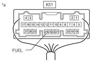
| *a | Component with harness connected
(Main Body ECU (Multiplex Network Body ECU)) |
Measure the voltage according to the value(s) in the table below.
- Standard Voltage:
Tester Connection Condition Specified Condition K51-24 (FUEL) - Body ground Fuel lid opener switch off 4.5 to 5.5 V
- Result:
Proceed to OK NG
OK
NG
Enter the following menus: Body Electrical / Main Body / Active Test.
Perform the Active Test according to the display on the GTS.
- Body Electrical > Main Body > Active Test
-
Tester Display Measurement Item Control Range Diagnostic Note Fuel Lid Opener Fuel lid lock with motor assembly OFF/ON -
- Body Electrical > Main Body > Active Test
-
Tester Display Fuel Lid Opener - 50004 123 65
| *a | Component with harness connected
(Main Body ECU (Multiplex Network Body ECU)) |
Measure the voltage according to the value(s) in the table below.
- Standard Voltage:
Tester Connection Condition Specified Condition K51-24 (FUEL) - Body ground Active Test Fuel Lid Opener OFF 4.5 to 5.5 V Active Test Fuel Lid Opener ON Below 1 V
- Result:
Proceed to OK NG
OK
NG
Remove the fuel lid lock with motor assembly.
Click hereVehicle Exterior>DOOR / HATCH>FUEL LID OPENER MOTOR ASSEMBLY>REMOVAL
Inspect the fuel lid lock with motor assembly (motor operation).
Click hereVehicle Exterior>DOOR / HATCH>FUEL LID OPENER MOTOR ASSEMBLY>INSPECTION
- Result:
Proceed to OK NG
OK
NG
Disconnect the 3C instrument panel junction block assembly connector.
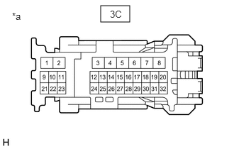
| *a | Front view of wire harness connector
(to Instrument Panel Junction Block Assembly) |
Measure the voltage according to the value(s) in the table below.
- Standard Voltage:
Tester Connection Condition Specified Condition 3C-7 - Body ground Power switch off 11 to 14 V 3C-30 - Body ground Power switch on (IG) 11 to 14 V Power switch off and fuel lid opener switch not pressed → fuel lid opener switch pressed for 0.8 second Below 1 V → 11 to 14 V
- Result:
Result Proceed to OK A The result for terminal 3C-7 is not as specified. B The result for terminal 3C-30 (with power switch on (IG)) is not as specified. The result for terminal 3C-30 (with power switch off and fuel lid opener switch pressed) is not as specified. C
A
B
C
Disconnect the A22 ECM connector.
Measure the resistance according to the value(s) in the table below.
- Standard Resistance:
Tester Connection Condition Specified Condition 3C-20 - A22-44 (FREL) Always Below 1 Ω 3C-20 or A22-44 (FREL) - Body ground Always 10 kΩ or higher
- Result:
Proceed to OK NG
OK
NG
Disconnect the 3D instrument panel junction block assembly connector.
Measure the resistance according to the value(s) in the table below.
- Standard Resistance:
Tester Connection Condition Specified Condition 3D-28 - W4-1 (B) Always Below 1 Ω 3D-28 or W4-1 (B) - Body ground Always 10 kΩ or higher
- Result:
Proceed to OK NG
OK
NG
Replace the instrument panel junction block assembly.
Click herePower Source / Network>POWER DISTRIBUTION>MAIN BODY ECU>REMOVAL
- Result:
Proceed to NEXT
NEXT
Check that the fuel lid can be opened.
Click hereVehicle Exterior>DOOR / HATCH>FUEL LID OPENER SYSTEM>OPERATION CHECK
- OK:
The fuel lid can be opened.
- Result:
Proceed to OK NG
OK
NG
Connect the GTS to the DLC3.
Turn the power switch on (IG).
Turn the GTS on.
Enter the following menus: Body Electrical / Main Body / Active Test.
Perform the Active Test according to the display on the GTS.
- Body Electrical > Main Body > Active Test
-
Tester Display Measurement Item Control Range Diagnostic Note Fuel Lid Opener Fuel lid lock with motor assembly OFF/ON -
- Body Electrical > Main Body > Active Test
-
Tester Display Fuel Lid Opener - 50004 123 52
- OK:
The fuel lid lock with motor assembly operates normally.
- Result:
Proceed to OK NG
OK
NG
Enter the following menus: Body Electrical / Main Body / Data List.
Read the Data List according to the display on the GTS.
- Body Electrical > Main Body > Data List
-
Tester Display Measurement Item Range Normal Condition Diagnostic Note Fuel Lid Opener Switch Fuel lid opener switch status OFF or ON OFF: Fuel lid opener switch not pushed
ON: Fuel lid opener switch pushed-
- OK:
The GTS display changes correctly in response to the operation of the fuel lid opener switch.
- Result:
Proceed to OK NG
OK
NG
Remove the fuel lid opener switch.
Click hereVehicle Exterior>DOOR / HATCH>FUEL LID OPENER SWITCH>REMOVAL
Inspect the fuel lid opener switch.
Click hereVehicle Exterior>DOOR / HATCH>FUEL LID OPENER SWITCH>INSPECTION
- Result:
Proceed to OK NG
OK
NG
Disconnect the K52 main body ECU (multiplex network body ECU) connector.
Measure the resistance according to the value(s) in the table below.
- Standard Resistance:
Tester Connection Condition Specified Condition K38-5 (IG) - K52-15 (FUSW) Always Below 1 Ω K38-2 (E) - Body ground Always Below 1 Ω K38-5 (IG) or K52-15 (FUSW) - Body ground Always 10 kΩ or higher
- Result:
Proceed to OK NG
OK
NG
Remove the fuel lid lock with motor assembly.
Click hereVehicle Exterior>DOOR / HATCH>FUEL LID OPENER MOTOR ASSEMBLY>REMOVAL
Inspect the fuel lid lock with motor assembly (motor operation).
Click hereVehicle Exterior>DOOR / HATCH>FUEL LID OPENER MOTOR ASSEMBLY>INSPECTION
- Result:
Proceed to OK NG
OK
NG
Disconnect the 3C instrument panel junction block assembly connector.
| *a | Front view of wire harness connector
(to Instrument Panel Junction Block Assembly) |
Measure the voltage according to the value(s) in the table below.
- Standard Voltage:
Tester Connection Condition Specified Condition 3C-7 - Body ground Power switch off 11 to 14 V 3C-30 - Body ground Power switch off 11 to 14 V
- Result:
Proceed to OK NG
OK
NG
Disconnect the 3A instrument panel junction block assembly connector.
Disconnect the K51 main body ECU (multiplex network body ECU) connector.
Measure the resistance according to the value(s) in the table below.
- Standard Resistance:
Tester Connection Condition Specified Condition 3A-19 - K51-24 (FUEL) Always Below 1 Ω 3A-19 or K51-24 (FUEL) - Body ground Always 10 kΩ or higher
- Result:
Proceed to OK NG
OK
NG
Disconnect the 3D instrument panel junction block assembly connector.
Measure the resistance according to the value(s) in the table below.
- Standard Resistance:
Tester Connection Condition Specified Condition 3D-28 - W4-1 (B) Always Below 1 Ω 3D-28 or W4-1 (B) - Body ground Always 10 kΩ or higher
- Result:
Proceed to OK NG
OK
NG
Replace the instrument panel junction block assembly.
Click herePower Source / Network>POWER DISTRIBUTION>MAIN BODY ECU>REMOVAL
- Result:
Proceed to NEXT
NEXT
Check that the fuel lid can be opened.
Click hereVehicle Exterior>DOOR / HATCH>FUEL LID OPENER SYSTEM>OPERATION CHECK
- OK:
The fuel lid can be opened.
- Result:
Proceed to OK NG
OK
NG