SUPPLEMENTAL RESTRAINT SYSTEMS STEERING PAD REMOVAL
CAUTION / NOTICE / HINT
The necessary procedures (adjustment, calibration, initialization or registration) that must be performed after parts are removed and installed, or replaced during horn button assembly removal/installation are shown below.
| Replaced Part or Performed Procedure | Necessary Procedure | Effect/Inoperative Function when Necessary Procedure not Performed | Link |
|---|---|---|---|
|
*: When performing learning using the GTS Click here( |
|||
| Disconnect cable from negative auxiliary battery terminal | Perform steering sensor zero point calibration | Lane departure alert system (w/ Steering Control) | ( ) |
| Parking Support Brake System* | |||
| Pre-collision system | |||
| Memorize steering angle neutral point | Parking assist monitor system | ()
|
|
PROCEDURE

 1. PRECAUTION
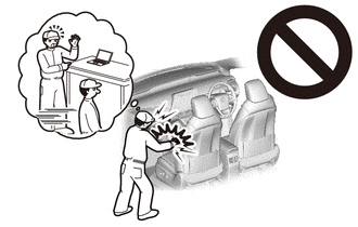
- CAUTION:
-
-
Be sure to read Precaution thoroughly before servicing.
-
Click hereVehicle Interior>SUPPLEMENTAL RESTRAINT SYSTEMS>AIRBAG SYSTEM>PRECAUTION
- NOTICE:
-
After turning the power switch off, waiting time may be required before disconnecting the cable from the negative (-) auxiliary battery terminal. Therefore, make sure to read the disconnecting the cable from the negative (-) auxiliary battery terminal notices before proceeding with work.
-
Click hereGeneral>INTRODUCTION>REPAIR INSTRUCTION>PRECAUTION
64718C
2.REMOVE LUGGAGE TRIM SERVICE HOLE COVER
3.DISCONNECT CABLE FROM NEGATIVE AUXILIARY BATTERY TERMINAL
Click hereGeneral>MAINTENANCE>AUXILIARY BATTERY>REMOVAL
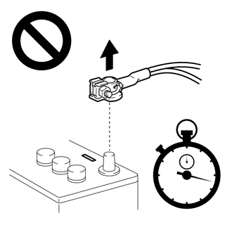
- CAUTION:
-
-
Wait at least 90 seconds after disconnecting the cable from the negative (-) auxiliary battery terminal to disable the SRS system.
- NOTICE:
-
When disconnecting the cable, some systems need to be initialized after the cable is reconnected.
-
Click hereGeneral>INTRODUCTION>REPAIR INSTRUCTION>INITIALIZATION
45186
4.REMOVE LOWER NO. 2 STEERING WHEEL COVER
Using a screwdriver with its tip wrapped with protective tape, disengage each claw to remove the 3 lower No. 2 steering wheel covers.
- HINT:
-
Be careful when disengaging the claws, as the lower No. 2 steering wheel cover may fly off.
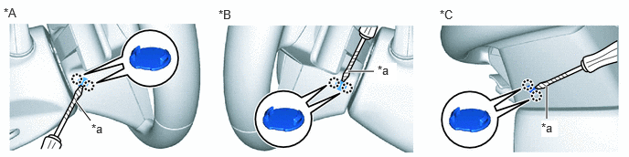
| *A | for LH Side | *B | for RH Side |
| *C | for Under Side | - | - |
| *a | Protective Tape | - | - |
45130
5.REMOVE HORN BUTTON ASSEMBLY
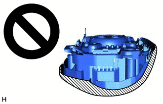
- CAUTION:
-
 0.948,0.958 1.104,1.156 0.156,0.198 10 false .

Deployment Side
-
When storing the horn button assembly, keep the airbag deployment side facing upward.
Check that the power switch is off.
Check that the cable is disconnected from the negative (-) auxiliary battery terminal.
- CAUTION:
-
-
Wait at least 90 seconds after disconnecting the cable from the negative (-) auxiliary battery terminal to disable the SRS system.
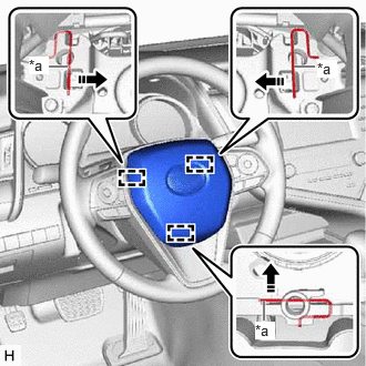
| *a | Torsion Spring |

|
Push in this Direction |
Using a screwdriver, push in the 3 torsion springs to disengage the 3 pins as shown in the illustration.
- NOTICE:
-
Lightly hold the horn button assembly so that it does not fall.
- HINT:
-
Insert the screwdriver from the installation holes for the 3 lower No. 2 steering wheel covers.
Pull out the horn button assembly from the steering wheel assembly and hold the horn button assembly with one hand.
- NOTICE:
-
When separating the horn button assembly, do not pull the airbag wire harness.
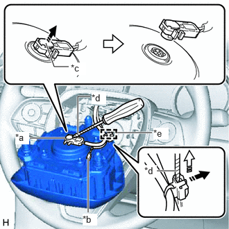
| *a | Airbag Connector |
| *b | Horn Connector |
| *c | Airbag Connector Locking Button |
| *d | Protective Tape |
| *e | Wire Harness Clamp |
|
|
Release in this Direction |

|
Remove in this Direction |
w/o Occupant Classification System:
Disconnect the horn connector from the horn button assembly.
Using a screwdriver with its tip wrapped with protective tape, release the airbag connector locking button.
Disconnect the airbag connector.
- NOTICE:
-
When disconnecting any airbag connector, take care not to damage the airbag wire harness.
Using a screwdriver with its tip wrapped with protective tape, release the lock and remove the wire harness clamp to remove the horn button assembly.
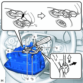
| *a | Airbag Connector |
| *b | Horn Connector |
| *c | Airbag Connector Locking Button |
| *d | Protective Tape |
| *e | Wire Harness Clamp |
|
|
Release in this Direction |
|
|
Remove in this Direction |
w/ Occupant Classification System:
Disconnect the horn connector from the horn button assembly.
Using a screwdriver with its tip wrapped with protective tape, release the 2 airbag connector locking buttons.
Disconnect the 2 airbag connectors.
- NOTICE:
-
When disconnecting any airbag connector, take care not to damage the airbag wire harness.
Using a screwdriver with its tip wrapped with protective tape, release the lock and remove the wire harness clamp to remove the horn button assembly.