VEHICLE PROXIMITY NOTIFICATION SYSTEM VEHICLE PROXIMITY NOTIFICATION SYSTEM(w/ Vehicle Approaching Speaker Switch) There is No Sound Made
DESCRIPTION
The vehicle approaching speaker controller receives stop light switch signals from the stop light switch assembly, vehicle speed signals from the combination meter assembly and permission signals from the hybrid vehicle control ECU assembly, and produces the warning sound from the vehicle approaching speaker assembly.
WIRING DIAGRAM
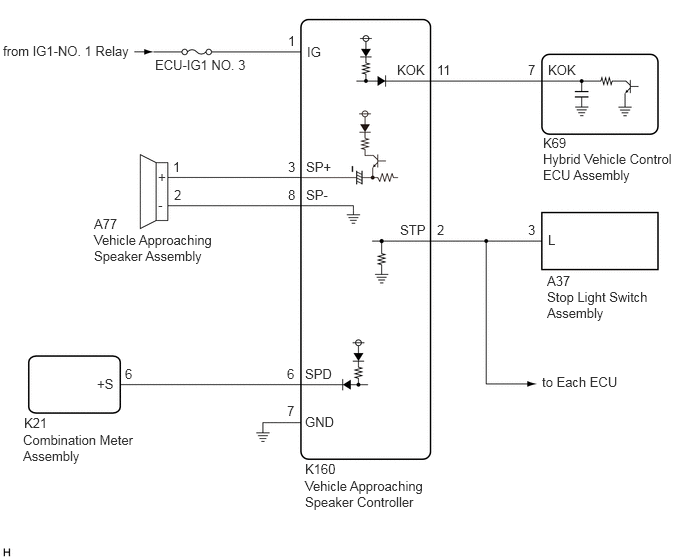
CAUTION / NOTICE / HINT
- NOTICE:
- ·
Before replacing the hybrid vehicle control ECU assembly, refer to Service Bulletin.
·Inspect the fuses for circuits related to this system before performing the following procedure.
·Make sure that the vehicle approaching speaker switch indicator is not illuminated before performing this procedure.
PROCEDURE
Connect the GTS to the DLC3.
Turn the power switch on (IG).
Turn the GTS on.
Enter the following menus: Body Electrical / Vehicle Proximity Notification System / Trouble Codes.
- Body Electrical > Vehicle Proximity Notification System > Trouble Codes
- 50001 359
- Result:
Result Proceed to B1350 is not output A B1350 is output B
A
B
Connect the GTS to the DLC3.
Turn the power switch on (IG).
Turn the GTS on.
Enter the following menus: Body Electrical / Vehicle Proximity Notification System / Active Test.
Perform the Active Test according to the display on the GTS.
- Body Electrical > Vehicle Proximity Notification System > Active Test
-
Tester Display Measurement Item Control Range Diagnostic Note Proximity Sound (Vehicle Stationary) Proximity sound (Vehicle stationary) OFF or ON Produces warning sound when vehicle is stopped
- Body Electrical > Vehicle Proximity Notification System > Active Test
-
Tester Display Proximity Sound (Vehicle Stationary) - 50004 359 2
- Result:
Result Proceed to The warning sound is produced A The warning sound is not produced B
A
B
Connect the GTS to the DLC3.
Turn the power switch on (IG).
Turn the GTS on.
Enter the following menus: Body Electrical / Vehicle Proximity Notification System / Data List.
Read the Data List according to the display on the GTS.
- Body Electrical > Vehicle Proximity Notification System > Data List
-
Tester Display Measurement Item Range Normal Condition Diagnostic Note Stop Light SW Stop light switch signal OFF or ON OFF: Brake pedal released
ON: Brake pedal depressed-
- Body Electrical > Vehicle Proximity Notification System > Data List
-
Tester Display Stop Light SW - 50003 359 5
- Result:
Result Proceed to The GTS display changes according to brake pedal operation A The GTS display does not change according to brake pedal operation B
A
B
Connect the GTS to the DLC3.
Turn the power switch on (IG).
Turn the GTS on.
Enter the following menus: Body Electrical / Vehicle Proximity Notification System / Data List.
Read the Data List according to the display on the GTS.
- Body Electrical > Vehicle Proximity Notification System > Data List
-
Tester Display Measurement Item Range Normal Condition Diagnostic Note Vehicle Speed Vehicle speed Min.: 0 km/h (0 mph), Max.: 255 km/h (158 mph) Almost the same as actual vehicle speed -
- Body Electrical > Vehicle Proximity Notification System > Data List
-
Tester Display Vehicle Speed - 50003 359 10
- Result:
Result Proceed to The GTS display changes according to the vehicle speed A The GTS display does not change according to the vehicle speed B
A
B
Connect the GTS to the DLC3.
Turn the power switch on (IG).
Turn the GTS on.
Enter the following menus: Body Electrical / Vehicle Proximity Notification System / Data List.
Read the Data List according to the display on the GTS.
- Body Electrical > Vehicle Proximity Notification System > Data List
-
Tester Display Measurement Item Range Normal Condition Diagnostic Note Permission Signal Vehicle proximity notification system permission signal OFF or ON OFF: Vehicle proximity notification system operation prohibited (engine is operating or shift lever is in P).
ON: Vehicle proximity notification system operation permitted (engine is stopped and shift lever is not in P).-
- Body Electrical > Vehicle Proximity Notification System > Data List
-
Tester Display Permission Signal - 50003 359 8
- Result:
Result Proceed to The GTS display changes according to the engine status or the shift lever position A The GTS display does not change according to the engine status or the shift lever position B
A
Click hereVehicle Exterior>VEHICLE PROXIMITY NOTIFICATION SYSTEM>VEHICLE APPROACHING SPEAKER ECU>REMOVAL
B
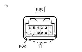
| *a | Component with harness connected
(Vehicle Approaching Speaker Controller) |
Measure the voltage according to the value(s) in the table below.
- Standard Voltage:
Tester Connection Condition Specified Condition K160-11 (KOK) - Body ground Power switch on (READY), shift lever in P Below 2.3 V Power switch on (READY), engine stopped and shift lever not in P 8 V or higher
- Result:
Proceed to OK NG
OK
Click hereVehicle Exterior>VEHICLE PROXIMITY NOTIFICATION SYSTEM>VEHICLE APPROACHING SPEAKER ECU>REMOVAL
NG
Disconnect the K160 vehicle approaching speaker controller connector.
Disconnect the K69 hybrid vehicle control ECU assembly connector.
Measure the resistance according to the value(s) in the table below.
- Standard Resistance:
Tester Connection Condition Specified Condition K160-11 (KOK) - K69-7 (KOK) Always Below 1 Ω K160-11 (KOK) or K69-7 (KOK) - Body ground Always 10 kΩ or higher
- Result:
Proceed to OK NG
OK
NG
Replace the vehicle approaching speaker controller with a new or known good one.
Click hereVehicle Exterior>VEHICLE PROXIMITY NOTIFICATION SYSTEM>VEHICLE APPROACHING SPEAKER ECU>REMOVAL
- OK:
The operation of the vehicle proximity notification system returns to normal.
- Result:
Proceed to OK NG
OK
NG
Disconnect the K21 combination meter assembly connector.
Disconnect the K160 vehicle approaching speaker controller connector.
Measure the resistance according to the value(s) in the table below.
- Standard Resistance:
Tester Connection Condition Specified Condition K21-6 (+S) - K160-6 (SPD) Always Below 1 Ω K21-6 (+S) or K160-6 (SPD) - Body ground Always 10 kΩ or higher
- Result:
Proceed to OK NG
OK
NG
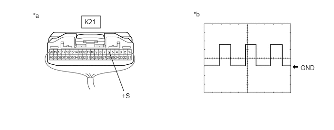
| *a | Component with harness connected
(Combination Meter Assembly) |
*b | Waveform |
Connect the K160 vehicle approaching speaker controller connector.
Connect the K21 combination meter assembly connector.
Check the input waveform.
- NOTICE:
-
Remove the combination meter assembly with the connector(s) still connected.
- OK:
Tester Connection Condition Tool Setting Specified Condition K21-6 (+S) - Body ground Vehicle being driven at approx. 20 km/h (12 mph) 5 V/DIV., 20 ms./DIV. Pulse generation
(See waveform)
- Result:
Proceed to OK NG
OK
Click hereVehicle Exterior>VEHICLE PROXIMITY NOTIFICATION SYSTEM>VEHICLE APPROACHING SPEAKER ECU>REMOVAL
NG
Check that the stop lights come on when the brake pedal is depressed, and go off when the brake pedal is released.
- OK:
Stop lights illuminate properly.
- Result:
Proceed to OK NG
OK
NG
w/ Automatic Headlight Beam Level Control System: Click hereVehicle Exterior>LIGHTING (EXT)>LIGHTING SYSTEM (w/ Automatic Headlight Beam Level Control System)>HOW TO PROCEED WITH TROUBLESHOOTING
w/o Automatic Headlight Beam Level Control System: Click hereVehicle Exterior>LIGHTING (EXT)>LIGHTING SYSTEM (w/o Automatic Headlight Beam Level Control System)>HOW TO PROCEED WITH TROUBLESHOOTING
Disconnect the K160 vehicle approaching speaker controller connector.
Disconnect the A37 stop light switch assembly connector.
Disconnect each ECU connector.
Measure the resistance according to the value(s) in the table below.
- Standard Resistance:
Tester Connection Condition Specified Condition K160-2 (STP) - A37-3 (L) Always Below 1 Ω K160-2 (STP) or A37-3 (L) - Body ground Always 10 kΩ or higher
- Result:
Proceed to OK NG
OK
Click hereVehicle Exterior>VEHICLE PROXIMITY NOTIFICATION SYSTEM>VEHICLE APPROACHING SPEAKER ECU>REMOVAL
NG
Remove the vehicle approaching speaker assembly.
Inspect the vehicle approaching speaker assembly.
- Result:
Proceed to OK NG
OK
NG
Disconnect the K160 vehicle approaching speaker controller connector.
Measure the resistance according to the value(s) in the table below.
- Standard Resistance:
Tester Connection Condition Specified Condition A77-1 (+) - K160-3 (SP+) Always Below 1 Ω A77-2 (-) - K160-8 (SP-) Always Below 1 Ω A77-1 (+) or K160-3 (SP+) - Body ground Always 10 kΩ or higher A77-2 (-) or K160-8 (SP-) - Body ground Always 10 kΩ or higher
- Result:
Proceed to OK NG
OK
Click hereVehicle Exterior>VEHICLE PROXIMITY NOTIFICATION SYSTEM>VEHICLE APPROACHING SPEAKER ECU>REMOVAL
NG