EXTERIOR PANELS / TRIM GRILLE SHUTTER SYSTEM Grille Shutter does not Operate
DESCRIPTION
The grille shutter of the radiator shutter sub-assembly may not operate when dirty due to foreign matter, snow, mud, etc., or the power supply voltage deteriorates.
WIRING DIAGRAM
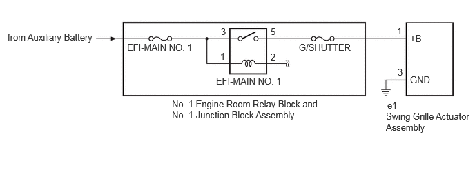
CAUTION / NOTICE / HINT
- NOTICE:
- ·
Before performing troubleshooting, change the grille shutter control mode to maintenance mode.
w/ Canister Pump Module: Click hereEngine / Hybrid System>A25A-FXS (ENGINE CONTROL)>SFI SYSTEM (w/ Canister Pump Module)>INITIALIZATION
w/o Canister Pump Module: Click hereEngine / Hybrid System>A25A-FXS (ENGINE CONTROL)>SFI SYSTEM (w/o Canister Pump Module)>INITIALIZATION
·If the radiator shutter assembly has been replaced with a new one, perform initialization and change the grille shutter control mode.
w/ Canister Pump Module: Click hereEngine / Hybrid System>A25A-FXS (ENGINE CONTROL)>SFI SYSTEM (w/ Canister Pump Module)>INITIALIZATION
w/o Canister Pump Module: Click hereEngine / Hybrid System>A25A-FXS (ENGINE CONTROL)>SFI SYSTEM (w/o Canister Pump Module)>INITIALIZATION
·Inspect the fuses for circuits related to this system before performing the following procedure.
PROCEDURE
According to the display on the GTS, change the grille shutter control mode from normal mode to maintenance mode.
- Powertrain > Engine > Utility
-
Tester Display Switch Grille Shutter Control Mode - 50005 372 5672
- Result:
Proceed to NEXT
NEXT
Check the area around the shutters and the links of the grille shutter for foreign matter and ice.
- OK:
The radiator shutter sub-assembly is free of foreign matter and ice.
- Result:
Proceed to OK NG
OK
NG
Remove the radiator shutter assembly.
Click hereVehicle Exterior>EXTERIOR PANELS / TRIM>GRILLE SHUTTER>REMOVAL
While using fingers to pinch the fin at the location shown in the illustration, fully open and close the radiator shutter assembly manually and check that it moves smoothly.
- HINT:
-
If the fin is pinched with fingers far from the swing grille actuator assembly, the function may not be able to be inspected correctly.
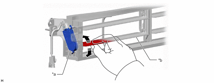
| *a | Swing Grille Actuator Assembly | *b | Fin |
- OK:
Radiator shutter sub-assembly moves smoothly.
Install the radiator shutter assembly.
Click hereVehicle Exterior>EXTERIOR PANELS / TRIM>GRILLE SHUTTER>INSTALLATION
- Result:
Proceed to OK NG
OK
NG
Clear the DTCs.
- Powertrain > Engine > Clear DTCs
- 50002 372
Turn the ignition switch off and wait for at least 30 seconds.
- Result:
Proceed to NEXT
NEXT
Check for DTCs.
- Powertrain > Engine > Trouble Codes
- 50001 372
- Result:
Result Proceed to DTCs are not output. OK DTCs are output. NG
OK
NG
w/ Canister Pump Module: Click hereEngine / Hybrid System>A25A-FXS (ENGINE CONTROL)>SFI SYSTEM (w/ Canister Pump Module)>DIAGNOSTIC TROUBLE CODE CHART
w/o Canister Pump Module: Click hereEngine / Hybrid System>A25A-FXS (ENGINE CONTROL)>SFI SYSTEM (w/o Canister Pump Module)>DIAGNOSTIC TROUBLE CODE CHART
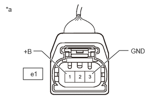
| *a | Front view of wire harness connector
(to Swing Grille Actuator Assembly) |
Disconnect the e1 swing grille actuator assembly connector.
Measure the voltage according to the value(s) in the table below.
- Standard Voltage:
Tester Connection Condition Specified Condition e1-1 (+B) - Body ground Ignition switch ON 11 to 14 V
Measure the resistance according to the value(s) in the table below.
- Standard Resistance:
Tester Connection Condition Specified Condition e1-3 (GND) - Body ground Always Below 1 Ω
Connect the e1 swing grille actuator assembly connector.
- Result:
Proceed to OK NG
OK
NG
According to the display on the GTS, change the grille shutter control mode from maintenance mode to normal mode.
- Powertrain > Engine > Utility
-
Tester Display Switch Grille Shutter Control Mode - 50005 372 5672
Read the value displayed on the GTS.
- Powertrain > Engine > Data List
-
Tester Display Measurement Item Range Normal Condition Diagnostic Note Grille Shutter Control Mode Grille shutter control mode status Normal or Maintenance Normal: Normal mode
Maintenance: Maintenance mode-
- Powertrain > Engine > Data List
-
Tester Display Grille Shutter Control Mode - 50003 372 1304
- OK:
Normal is displayed.
- Result:
Proceed to NEXT
NEXT
- HINT:
-
Operation temporarily abnormal due to fail-safe (abnormal temperature).
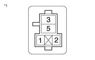
| *1 | No. 1 Engine Room Relay Block and No. 1 Junction Block Assembly
(EFI-MAIN NO. 1 Relay Holder) |
Remove the EFI-MAIN NO. 1 relay from the No. 1 engine room relay block and No. 1 junction block assembly.
Disconnect the e1 swing grille actuator assembly connector.
Measure the resistance according to the value(s) in the table below.
- Standard Resistance:
Tester Connection Condition Specified Condition e1-1 (+B) - No. 1 engine room relay block and No. 1 junction block assembly EFI-MAIN NO. 1 relay terminal 5 Always Below 1 Ω e1-1 (+B) or No. 1 engine room relay block and No. 1 junction block assembly EFI-MAIN NO. 1 relay terminal 5 - Body ground Always 10 kΩ or higher
Install the EFI-MAIN NO. 1 relay from the No. 1 engine room relay block and No. 1 junction block assembly.
Connect the e1 swing grille actuator assembly connector.
- Result:
Proceed to OK NG
OK
NG
Check the ECM power source circuit.
- Result:
Proceed to NEXT
NEXT
Remove any foreign matter and/or ice from the area around the shutters and the links of the grille shutter.
- Result:
Proceed to NEXT
NEXT