Home › Engine / Hybrid System › 1BZ-FPE (ENGINE CONTROL) › ELECTRONIC CONTROLLED CARBURETOR SYSTEM › 2017.01–2021.01
RM2850E _51 Engine / Hybrid System _073136 1BZ-FPE ENGINE CONTROL _0355837 ELECTRONIC CONTROLLED CARBURETOR SYSTEM C

1BZ-FPE ENGINE CONTROL  ELECTRONIC CONTROLLED CARBURETOR SYSTEM  P0115  Engine Coolant Temperature Circuit  


DESCRIPTION

A thermistor built into the water temp. sensor changes the resistance value according to the water temp. The structure of the sensor and connection to the engine ECU is the same as in the DTC P0110 (Intake air temp. circuit malfunction) shown on page Click hereEngine / Hybrid System>1BZ-FPE (ENGINE CONTROL)>ELECTRONIC CONTROLLED CARBURETOR SYSTEM>P0110.

DTC No. DTC Detecting Condition Trouble Area
P0115/22 Open or short in water temp. sensor circuit 0.5 sec or more
·

Open or short in water temp. sensor circuit

·

Water temp. sensor

·

Engine ECU


HINT:

After confirming DTC P0115 use the hand-held tester to confirm the water temp. from CURRENT DATA.


Temp. Displayed Malfunction
- 40°C (- 40°F) Open circuit
140°C (284°F) or more Short circuit

WIRING DIAGRAM

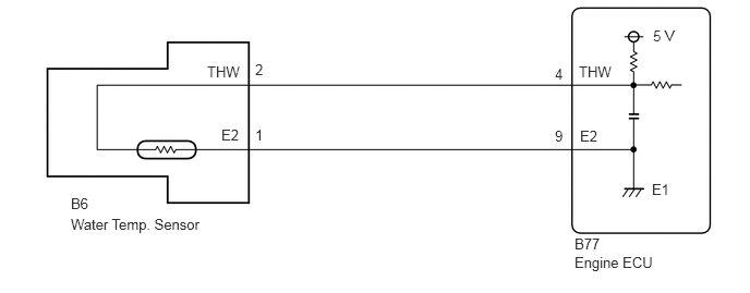
A401742E01
1.979,0.604 2.438,0.802 0.458,0.198 10 false THW 2.115,1.208 2.427,1.417 0.313,0.208 10 false E2 2.438,0.583 2.635,0.781 0.198,0.198 10 false 2 2.438,1.208 2.635,1.406 0.198,0.198 10 false 1 0.677,1.865 0.948,2.052 0.271,0.188 10 false B6 0.677,2.063 2.073,2.25 1.396,0.188 10 false Water Temp. Sensor 5.302,0.625 5.521,0.854 0.219,0.229 10 false 4 5.302,1.219 5.479,1.417 0.177,0.198 10 false 9 5.531,0.604 5.99,0.802 0.458,0.198 10 false THW 5.542,1.219 5.865,1.427 0.323,0.208 10 false E2 6.24,0.26 6.552,0.51 0.313,0.25 10 false 5 V 6.229,1.729 6.469,1.927 0.24,0.198 10 false E1 5.49,2.25 5.833,2.448 0.344,0.198 10 false B77 5.49,2.427 6.406,2.646 0.917,0.219 10 false Engine ECU

CAUTION / NOTICE / HINT

HINT:
·

Read freed frame data using hand-held tester. Because freeze frame records the engine conditions when the malfunction is detected, when troubleshooting it is useful for determining whether the vehicle was running or stopped, the engine warmed up or not, the air-fuel ratio lean or rich, etc. at the time of the malfunction.

·

If DTC "P0105" (Vacuum Sensor Circuit Malfunction), "P0110" (Intake Air Temp. Circuit Malfunction), "P0115" (Water Temp. Circuit Malfunction), "P0120" (Throttle Position Sensor Circuit Malfunction) are output simultaneously, E2 (Sensor Ground) may be open.


PROCEDURE

1.Connect the hand-held tester, and read value of water temp.

PREPARATION:

a.

Connect the hand-held tester to the DLC3.


b.

Turn ignition switch ON and push the hand-held tester main switch ON.


CHECK:

Read temp. value on the hand-held tester.

OK:

Same as actual water temp.


HINT:
·

If there is open circuit, hand-held tester indicates -40°C (- 40°F).

·

If there is short hand-held tester indicates 140°C (284°F) or more.


Result:
Result Proceed to
Same as actual water temp A
-40°C (-40°F) B
140°C (284°F) or more C


A

B

2.Check for short in harness or engine ECU.

C

4.Check for short in harness or engine ECU.
2.Check for short in harness or engine ECU.
A429923E03
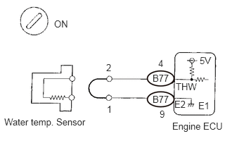
0.802,0.271 1.125,0.469 0.323,0.198 10 false ON 0.063,1.719 1.396,1.948 1.333,0.229 10 false Water temp. Sensor 1.573,0.917 1.896,1.146 0.323,0.229 10 false 2 1.583,1.531 1.896,1.729 0.313,0.198 10 false 1 2.344,0.854 2.656,1.052 0.313,0.198 10 false 4 2.365,1.604 2.677,1.802 0.313,0.198 10 false 9 2.604,1.198 2.958,1.385 0.354,0.188 10 false THW 2.958,0.813 3.271,1.01 0.313,0.198 10 false 5V 2.583,1.458 2.833,1.646 0.25,0.188 10 false E2 2.938,1.479 3.25,1.677 0.313,0.198 10 false E1 2.26,1.073 2.573,1.271 0.313,0.198 10 false B77 2.26,1.385 2.573,1.583 0.313,0.198 10 false B77 2.552,1.781 3.354,1.99 0.802,0.208 10 false Engine ECU

PREPARATION:

a.

Disconnect the water temp. sensor connector.


b.

Connect sensor wire harness terminals together.


c.

Turn ignition switch ON.


CHECK:

Read temp. value on the hand-held tester.

OK:

Temp. value: 140°C (284°F) or more


Result:
Proceed to
OK
NG


OK

Confirm good connection at sensor. If OK, replace water temp. sensor.

NG

3.Check for open in harness or engine ECU.
A429927E01
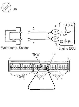
1.573,2.49 1.802,2.885 true 2.063,2.99 2.323,2.458 true 2.281,1.313 2.594,1.51 0.313,0.198 10 false B77 2.281,1.625 2.594,1.823 0.313,0.198 10 false B77 0.542,0.302 0.854,0.5 0.313,0.198 10 false ON 0.052,2 1.417,2.219 1.365,0.219 10 false Water temp. Sensor 1.427,1.167 1.604,1.365 0.177,0.198 10 false 2 1.427,1.802 1.646,1.979 0.219,0.177 10 false 1 2.375,1.052 2.552,1.229 0.177,0.177 10 false 4 2.406,1.854 2.583,2.063 0.177,0.208 10 false 9 2.979,1.042 3.271,1.24 0.292,0.198 10 false 5 V 2.594,1.448 2.979,1.646 0.385,0.198 10 false THW 2.594,1.729 2.906,1.927 0.313,0.198 10 false E2 2.958,1.74 3.177,1.938 0.219,0.198 10 false E1 2.542,2.031 3.344,2.25 0.802,0.219 10 false Engine ECU 1.406,2.302 1.844,2.521 0.438,0.219 10 false THW 2.25,2.281 2.563,2.479 0.313,0.198 10 false E2

PREPARATION:

a.

Remove the side trim bracket.


b.

Connect between terminals THW and E2 of engine ECU connector.

HINT:

Water temp. sensor connector is disconnected. Before checking, do a visual and contact pressure check for the engine ECU connector (Click hereGeneral>INTRODUCTION>HOW TO TROUBLESHOOT ECU CONTROLLED SYSTEMS>ELECTRONIC CIRCUIT INSPECTION PROCEDURE).


c.

Turn ignition switch ON.


CHECK:

Read temp. value on the hand-held tester.

OK:

Temp. value: 140°C (284°F) or more


Result:
Proceed to
OK
NG


OK

Open in harness between terminals E2 or THW, repair or replace harness.

NG

Confirm good connection at engine ECU. If OK, replace engine ECU.

4.Check for short in harness or engine ECU.
A429925E02
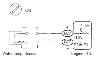
0.083,1.802 1.677,2.01 1.594,0.208 10 false Water temp. Sensor 0.885,0.281 1.198,0.479 0.313,0.198 10 false ON 1.271,0.927 1.469,1.135 0.198,0.208 10 false 2 1.271,1.563 1.469,1.75 0.198,0.188 10 false 1 2.313,0.875 2.521,1.073 0.208,0.198 10 false 4 2.25,1.094 2.563,1.292 0.313,0.198 10 false B77 2.333,1.625 2.552,1.833 0.219,0.208 10 false 9 2.5,1.802 3.271,2.042 0.771,0.24 10 false Engine ECU 2.927,1.5 3.167,1.667 0.24,0.167 10 false E1 2.969,0.813 3.281,1.01 0.313,0.198 10 false 5V 2.583,1.229 2.99,1.438 0.406,0.208 10 false THW 2.25,1.396 2.563,1.594 0.313,0.198 10 false B77 2.583,1.5 2.823,1.667 0.24,0.167 10 false E2

PREPARATION:

a.

Disconnect the water temp. sensor connector.


b.

Turn ignition switch ON.


CHECK:

Read temp. value on the hand-held tester.

OK:

Temp. value: -40°C (- 40°F)


Result:
Proceed to
OK
NG


OK

Replace water temp. sensor.

NG

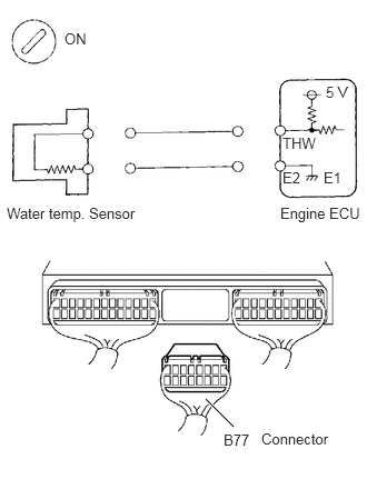
5.Check for short in harness of engine ECU.
A398965E02
1.927,3.74 2.188,4 true 0.604,0.281 0.917,0.479 0.313,0.198 10 false ON 0.063,1.917 1.458,2.146 1.396,0.229 10 false Water temp. Sensor 2.625,1.917 3.406,2.146 0.781,0.229 10 false Engine ECU 3.052,0.781 3.365,0.979 0.313,0.198 10 false 5 V 2.646,1.26 3.042,1.458 0.396,0.198 10 false THW 2.646,1.583 2.958,1.781 0.313,0.198 10 false E2 3.031,1.583 3.344,1.781 0.313,0.198 10 false E1 2.094,4.042 2.417,4.229 0.323,0.188 10 false B77 2.448,4.031 3.208,4.25 0.76,0.219 10 false Connector

PREPARATION:

a.

Remove the side trim bracket.


b.

Disconnect the connector of engine ECU.

HINT:

Water temp. sensor connector is disconnected.


c.

Turn ignition switch ON.


CHECK:

Read temp. value on the hand-held tester.

OK:

Temp. value: -40°C (- 40°F)


Result:
Proceed to
OK
NG


OK

Repair or replac harness or connector.

NG