RM2850E
_51
Engine / Hybrid System
_073136
1BZ-FPE ENGINE CONTROL
_0355837
ELECTRONIC CONTROLLED CARBURETOR SYSTEM
J
1BZ-FPE ENGINE CONTROL ELECTRONIC CONTROLLED CARBURETOR SYSTEM Injector Circuit
DESCRIPTION
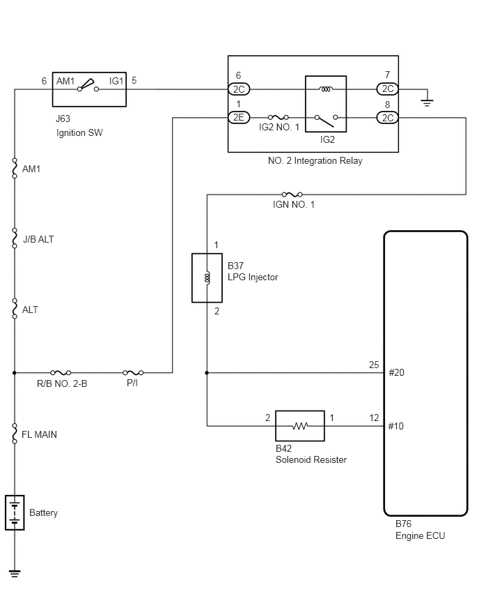
The injectors are situated in the carburetor. They inject fuel into the intake manifold based on the signals from the engine ECU.
- Reference:
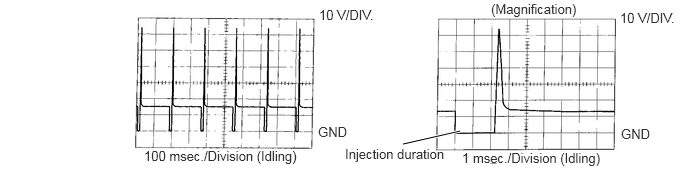
INSPECTION USING OSCILLOSCOPE
With the engine idling, check the waveform between terminals #10 and E01 of the engine ECU connector.
- HINT:
-
The correct waveform is as shown.
4.198,1.5 4.792,1.365
true
3.323,0.073 4.083,0.302
0.76,0.229
10
false
10 V/DIV.
5.115,0.01 6.156,0.219
1.042,0.208
10
false
(Magnification)
6.458,0.104 7.115,0.344
0.656,0.24
10
false
10 V/DIV.
6.469,1.313 6.917,1.552
0.448,0.24
10
false
GND
3.313,1.292 3.76,1.531
0.448,0.24
10
false
GND
1.5,1.542 3.167,1.75
1.667,0.208
10
false
100 msec./Division (Idling)
3.594,1.521 4.708,1.698
1.115,0.177
10
false
Injection duration
4.813,1.563 6.521,1.76
1.708,0.198
10
false
1 msec./Division (Idling)
WIRING DIAGRAM
0.844,1.125 1.302,1.323
0.458,0.198
10
false
AM1
0.625,1.125 0.844,1.333
0.219,0.208
10
false
6
0.833,1.688 1.167,1.917
0.333,0.229
10
false
J63
0.844,1.896 1.771,2.115
0.927,0.219
10
false
Ignition SW
1.635,1.125 1.969,1.323
0.333,0.198
10
false
IG1
1.969,1.115 2.188,1.323
0.219,0.208
10
false
5
3.531,1.042 3.75,1.25
0.219,0.208
10
false
6
3.49,1.25 3.823,1.479
0.333,0.229
10
false
2C
3.531,1.469 3.75,1.677
0.219,0.208
10
false
1
3.49,1.667 3.708,1.875
0.219,0.208
10
false
2E
3.875,1.813 4.573,2
0.698,0.188
10
false
IG2 NO. 1
4.792,2 5.146,2.167
0.354,0.167
10
false
IG2
5.76,1.031 5.979,1.24
0.219,0.208
10
false
7
5.719,1.24 6,1.469
0.281,0.229
10
false
2C
5.76,1.479 5.979,1.688
0.219,0.208
10
false
8
5.719,1.677 6.042,1.906
0.323,0.229
10
false
2C
4.01,2.313 5.51,2.552
1.5,0.24
10
false
NO. 2 Integration Relay
4.083,2.969 4.917,3.219
0.833,0.25
10
false
IGN NO. 1
3.198,3.573 3.417,3.781
0.219,0.208
10
false
1
3.406,3.885 3.792,4.104
0.385,0.219
10
false
B37
3.406,4.052 4.313,4.313
0.906,0.26
10
false
LPG Injector
3.208,4.563 3.427,4.771
0.219,0.208
10
false
2
5.521,5.365 5.771,5.594
0.25,0.229
10
false
25
5.823,5.479 6.229,5.708
0.406,0.229
10
false
#20
5.813,6.281 6.167,6.51
0.354,0.229
10
false
#10
5.521,6.156 5.792,6.375
0.271,0.219
10
false
12
4.927,6.156 5.146,6.365
0.219,0.208
10
false
1
3.969,6.156 4.188,6.365
0.219,0.208
10
false
2
4.125,6.615 4.5,6.844
0.375,0.229
10
false
B42
4.125,6.781 5.49,7.052
1.365,0.271
10
false
Solenoid Resister
1.896,5.635 2.219,5.865
0.323,0.229
10
false
P/I
0.552,5.646 1.417,5.885
0.865,0.24
10
false
R/B NO. 2-B
0.333,4.542 0.719,4.771
0.385,0.229
10
false
ALT
0.344,3.49 0.938,3.708
0.594,0.219
10
false
J/B ALT
0.333,2.438 0.76,2.656
0.427,0.219
10
false
AM1
0.323,6.406 1.125,6.667
0.802,0.26
10
false
FL MAIN
0.438,7.573 1.365,7.844
0.927,0.271
10
false
Battery
5.917,7.74 6.271,7.979
0.354,0.24
10
false
B76
5.917,7.917 6.979,8.167
1.063,0.25
10
false
Engine ECU
CAUTION / NOTICE / HINT
- NOTICE:
-
Inspect the fuses for circuits related to this system before performing the following procedure.
PROCEDURE
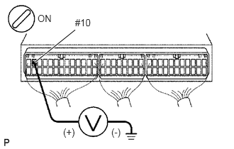
1.Check voltage between terminal #10 of engine ECU and body ground.
0.51,0.917 1.104,0.438
true
0.552,0.188 0.865,0.385
0.313,0.198
10
false
ON
1.104,0.25 1.417,0.448
0.313,0.198
10
false
#10
0.927,1.854 1.24,2.052
0.313,0.198
10
false
(+)
1.635,1.854 1.948,2.052
0.313,0.198
10
false
(-)
PREPARATION:
a.
Remove the side trim bracket.
b.
Turn the ignition switch ON.
CHECK:
Measure the voltage between terminal #10 of the engine ECU connector and body ground.
- OK:
Voltage: 9 - 14 V
- Result:
Proceed to OK NG
OK
Check and replace engine ECU.
NG
2.Check injector resistance.
2.Check injector resistance.
- Result:
Proceed to OK NG
OK
3.Check ignition switch.
NG
Replace injector.
3.Check ignition switch.
Click hereEngine / Hybrid System>1BZ-FPE (STARTING)>IGNITION SWITCH>INSPECTION
- Result:
Proceed to OK NG
OK
Check for open in harness and connector between engine ECU and battery.
NG
Replace ignition switch.