Home › Engine / Hybrid System › 1BZ-FPE (ENGINE CONTROL) › ELECTRONIC CONTROLLED CARBURETOR SYSTEM › 2017.01–2021.01
RM2850E _51 Engine / Hybrid System _073136 1BZ-FPE ENGINE CONTROL _0355837 ELECTRONIC CONTROLLED CARBURETOR SYSTEM J

1BZ-FPE ENGINE CONTROL  ELECTRONIC CONTROLLED CARBURETOR SYSTEM  Emergency Engine Stop Button Circuit  


DESCRIPTION

When the engine stop switch is pushed, battery voltage is not applied to the coil, open the contacts of the engine stop relay.

That the voltage becomes not to be applied to the terminal +B of the engine ECU will result in stopping the engine.

WIRING DIAGRAM
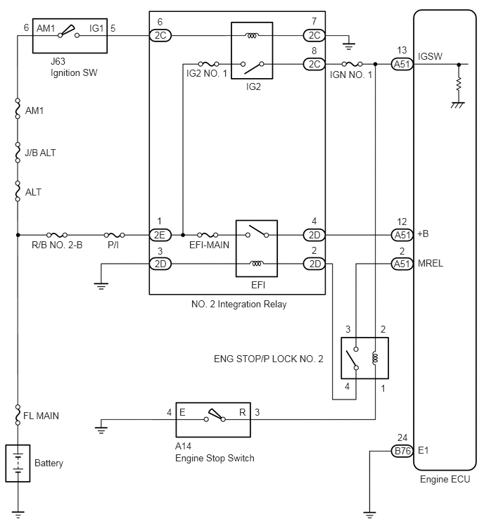
A403041E01
0.354,0.323 0.563,0.552 0.208,0.229 10 false 6 0.542,0.333 0.917,0.573 0.375,0.24 10 false AM1 1.323,0.333 1.656,0.563 0.333,0.229 10 false IG1 1.635,0.333 1.844,0.563 0.208,0.229 10 false 5 0.75,0.823 1.052,1.052 0.302,0.229 10 false J63 0.75,0.99 1.552,1.25 0.802,0.26 10 false Ignition SW 0.375,1.552 0.813,1.771 0.438,0.219 10 false AM1 0.365,2.177 0.927,2.396 0.563,0.219 10 false J/B ALT 0.375,2.76 0.813,2.979 0.438,0.219 10 false ALT 2.333,0.24 2.542,0.469 0.208,0.229 10 false 6 2.292,0.438 2.615,0.646 0.323,0.208 10 false 2C 2.76,1 3.479,1.219 0.719,0.219 10 false IG2 NO. 1 3.646,1.198 4.042,1.375 0.396,0.177 10 false IG2 4.615,0.229 4.875,0.458 0.26,0.229 10 false 7 4.573,0.438 4.927,0.667 0.354,0.229 10 false 2C 4.615,0.667 4.844,0.896 0.229,0.229 10 false 8 4.573,0.865 4.875,1.083 0.302,0.219 10 false 2C 4.885,1.021 5.604,1.25 0.719,0.229 10 false IGN NO. 1 5.875,0.656 6.083,0.885 0.208,0.229 10 false 13 5.833,0.865 6.198,1.104 0.365,0.24 10 false A51 6.188,0.75 6.74,0.958 0.552,0.208 10 false IGSW 6.177,3.375 6.458,3.604 0.281,0.229 10 false +B 6.188,3.813 6.646,4.01 0.458,0.198 10 false MREL 5.875,3.198 6.146,3.406 0.271,0.208 10 false 12 5.844,3.396 6.198,3.573 0.354,0.177 10 false A51 5.917,3.635 6.115,3.844 0.198,0.208 10 false 2 5.833,3.823 6.135,4.042 0.302,0.219 10 false A51 4.615,3.188 4.823,3.417 0.208,0.229 10 false 4 4.573,3.396 4.875,3.625 0.302,0.229 10 false 2D 4.615,3.625 4.854,3.844 0.24,0.219 10 false 2 4.583,3.823 4.865,4.042 0.281,0.219 10 false 2D 3.719,4.135 4.031,4.365 0.313,0.229 10 false EFI 2.802,3.542 3.531,3.771 0.729,0.229 10 false EFI-MAIN 2.323,3.188 2.531,3.396 0.208,0.208 10 false 1 2.281,3.396 2.604,3.635 0.323,0.24 10 false 2E 2.333,3.635 2.542,3.865 0.208,0.229 10 false 3 2.292,3.823 2.583,4.052 0.292,0.229 10 false 2D 1.594,3.542 1.896,3.76 0.302,0.219 10 false P/I 0.469,3.542 1.333,3.771 0.865,0.229 10 false R/B NO. 2-B 2.833,4.417 4.344,4.667 1.51,0.25 10 false NO. 2 Integration Relay 5.115,4.792 5.323,5.021 0.208,0.229 10 false 3 5.635,4.792 5.844,5.021 0.208,0.229 10 false 2 5.635,5.667 5.844,5.896 0.208,0.229 10 false 1 5.104,5.635 5.313,5.865 0.208,0.229 10 false 4 3.167,5.229 4.875,5.448 1.708,0.219 10 false ENG STOP/P LOCK NO. 2 5.885,6.396 6.094,6.625 0.208,0.229 10 false 24 5.844,6.594 6.167,6.771 0.323,0.177 10 false B76 6.188,6.583 6.469,6.802 0.281,0.219 10 false E1 6.219,7.01 7.052,7.198 0.833,0.188 10 false Engine ECU 3.771,6.021 3.979,6.25 0.208,0.229 10 false 3 3.542,6.021 3.75,6.25 0.208,0.229 10 false R 2.656,6.021 2.865,6.25 0.208,0.229 10 false E 2.469,6.021 2.677,6.25 0.208,0.229 10 false 4 2.594,6.521 2.948,6.74 0.354,0.219 10 false A14 2.594,6.698 3.948,6.938 1.354,0.24 10 false Engine Stop Switch 0.51,6.771 1.115,7.021 0.604,0.25 10 false Battery 0.344,6.073 1,6.271 0.656,0.198 10 false FL MAIN

CAUTION / NOTICE / HINT

NOTICE:

Inspect the fuses for circuits related to this system before performing the following procedure.


PROCEDURE
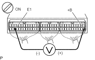
1.Check voltage between terminal +B and E1 of engine ECU connectors.
A403026E01
0.573,1.031 0.979,0.458 true 2.615,0.448 3.042,1.063 true 0.552,0.25 0.865,0.448 0.313,0.198 10 false ON 0.979,0.26 1.292,0.458 0.313,0.198 10 false E1 2.438,0.281 2.75,0.479 0.313,0.198 10 false +B 1.302,1.854 1.615,2.052 0.313,0.198 10 false (-) 2.094,1.844 2.406,2.042 0.313,0.198 10 false (+)

PREPARATION:

a.

Remove the side trim bracket.


b.

Turn the ignition switch ON.


CHECK:

Measure the voltage between terminals +B and E1 of the engine ECU connectors.

OK:

Voltage: 9 -14 V


Result:
Proceed to
OK
NG


OK

Proceed to next circuit inspection shown on problem symptoms table.

NG

2.Check NO. 2 integration relay.

OK

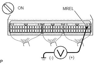
3.Check voltage between terminal MREL of engine ECU connector and body ground.

NG

Repair NO. 2 integration relay.

3.Check voltage between terminal MREL of engine ECU connector and body ground.
A403027E01
2.531,0.365 2.958,0.917 true 0.604,0.188 0.917,0.385 0.313,0.198 10 false ON 2.135,0.208 2.604,0.417 0.469,0.208 10 false MREL 1.677,1.885 1.99,2.083 0.313,0.198 10 false (-) 2.354,1.875 2.667,2.073 0.313,0.198 10 false (+)

PREPARATION:

a.

Remove the side trim bracket.


b.

Turn the ignition switch ON.


CHECK:

Measure the voltage between terminals MREL of the engine ECU connector and body ground.

OK:

Voltage: 9 -14 V


Result:
Proceed to
OK
NG


OK

NG

4.Check ENG STOP/P LOCK NO. 2 relay.

OK

5.Check engine stop switch.

NG

Repair ENG STOP/P LOCK NO. 2 relay.

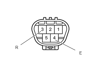
5.Check engine stop switch.
A403047E01
0.688,1.51 1.365,1.052 true 2.51,1.688 1.844,1.344 true 0.51,1.51 0.76,1.74 0.25,0.229 10 false R 2.646,1.698 2.896,1.927 0.25,0.229 10 false E

PREPARATION:

Disconnect the engine stop switch connector.

CHECK:

Check continuity between terminals 3 and 4 of engine stop switch connector.

OK:
Engine stop switch condition Specified condition
Press continuously engine stop switch Continuity
Release engine stoop switch No continuity

Result:
Proceed to
OK
NG


OK

Repair or replace harness or connector.

NG

Repair engine stop switch.