Home › Engine / Hybrid System › 1BZ-FPE (ENGINE CONTROL) › ELECTRONIC CONTROLLED CARBURETOR SYSTEM › 2017.01–2021.01
RM2850E _51 Engine / Hybrid System _073136 1BZ-FPE ENGINE CONTROL _0355837 ELECTRONIC CONTROLLED CARBURETOR SYSTEM J

1BZ-FPE ENGINE CONTROL  ELECTRONIC CONTROLLED CARBURETOR SYSTEM  Starter Signal Circuit  


DESCRIPTION

When the engine is cranked, the intake air flow is slow, so fuel vaporization is poor. A rich mixture is therefore necessary in order to achieve good startability. While the engine is being cranked, the battery positive voltage is applied to terminal STA of the engine ECU. The starter signal id mainly used to increase the fuel injection volume for the starting injection control and after-start injection control.

WIRING DIAGRAM
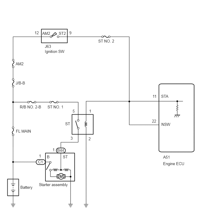
A403032E01
1.219,1.073 1.531,1.271 0.313,0.198 10 false 12 1.49,1.094 1.844,1.292 0.354,0.198 10 false AM2 2.073,1.094 2.469,1.302 0.396,0.208 10 false ST2 2.448,1.073 2.76,1.271 0.313,0.198 10 false 9 3.469,1.365 4.198,1.594 0.729,0.229 10 false ST NO. 2 1.583,1.552 1.896,1.75 0.313,0.198 10 false J63 1.583,1.729 2.646,1.938 1.063,0.208 10 false Ignition SW 0.552,2.167 1,2.385 0.448,0.219 10 false AM2 0.552,2.844 1.052,3.063 0.5,0.219 10 false J/B-B 0.698,3.688 1.563,3.917 0.865,0.229 10 false R/B NO. 2-B 1.677,3.688 2.365,3.906 0.688,0.219 10 false ST NO. 1 0.563,4.542 1.333,4.76 0.771,0.219 10 false FL MAIN 2.302,4.281 2.615,4.479 0.313,0.198 10 false ST 2.563,3.833 2.875,4.031 0.313,0.198 10 false 5 3.146,3.833 3.458,4.031 0.313,0.198 10 false 1 3.125,4.813 3.438,5.01 0.313,0.198 10 false 2 2.49,4.792 2.802,4.99 0.313,0.198 10 false 3 5.385,3.313 5.698,3.51 0.313,0.198 10 false 11 5.688,3.313 6.094,3.51 0.406,0.198 10 false STA 5.365,4.188 5.677,4.385 0.313,0.198 10 false 22 5.698,4.302 6.125,4.5 0.427,0.198 10 false NSW 5.76,5.458 6.073,5.656 0.313,0.198 10 false A51 5.76,5.688 6.688,5.906 0.927,0.219 10 false Engine ECU 2.021,5.219 2.385,5.469 0.365,0.25 10 false B44 1.854,5.198 2.052,5.396 0.198,0.198 10 false 1 1.375,5.417 1.688,5.615 0.313,0.198 10 false 1 1.344,5.625 1.656,5.823 0.313,0.198 10 false C1 1.656,5.448 1.969,5.646 0.313,0.198 10 false B 2.219,5.448 2.531,5.646 0.313,0.198 10 false ST 1.375,6.427 2.49,6.667 1.115,0.24 10 false Starter assembly 0.719,6.521 1.26,6.729 0.542,0.208 10 false Battery

CAUTION / NOTICE / HINT

NOTICE:

Inspect the fuses for circuits related to this system before performing the following inspection procedure.


HINT:

This inspection procedure is based on the premise that the engine can crank normally. If the engine cannot crank normally, proceed to the problem symptoms table (Click hereEngine / Hybrid System>1BZ-FPE (ENGINE CONTROL)>ELECTRONIC CONTROLLED CARBURETOR SYSTEM>PROBLEM SYMPTOMS TABLE).


PROCEDURE

1.Connect hand-held tester and check STA signal.

PREPARATION:

a.

Connect the hand-held tester to the DLC3.


b.

Turn the ignition switch ON and push the hand-held tester main switch ON.


CHECK:

Read STA signal on the hand-held tester while starter operates.

OK:
Ignition Switch Position ON START
STA signal OFF ON


Result:
Proceed to
OK
NG


OK

Proceed to next circuit inspection shown on problem symptoms table.

NG

2.Check ignition switch.

OK

3.Check for open in harness and connector.

NG

Replace ignition switch.

3.Check for open in harness and connector.

OK

NG

Repair or replace harness or connector.