RM2850E
_51
Engine / Hybrid System
_073137
N04C-UH ENGINE CONTROL
_0355844
ECD SYSTEM
C
N04C-UH ENGINE CONTROL ECD SYSTEM P0863 TCM Communication Circuit
DESCRIPTION
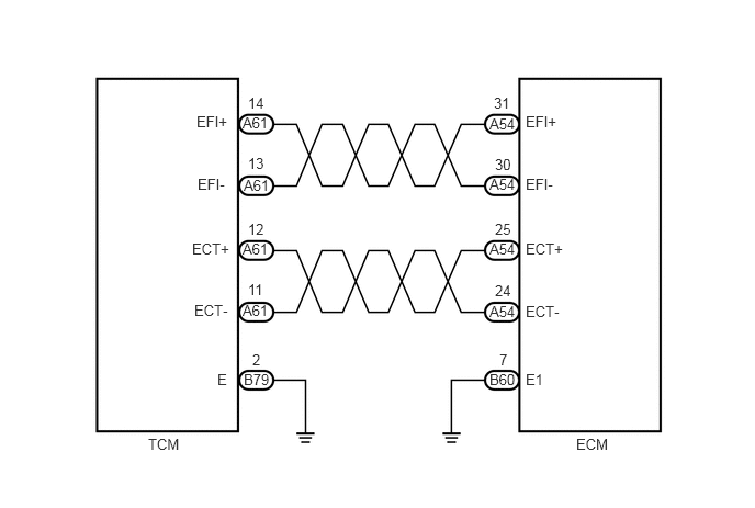
ECM receives lock-up condition and shift position from TCM. And ECM sends accelerator position and idling signal to TCM.
| DTC No. | DTC Detection Condition | Trouble Area |
|---|---|---|
| P0863 | All conditions below are detected continuously for 5 seconds or more:
(1 trip detection logic) (a) Ignition switch ON. (b) Communication error between ECM and TCM. |
·
Open or short in communication circuit between ECM and TCM ·
ECM ·
TCM |
WIRING DIAGRAM
2.354,2.667 2.563,2.875
0.208,0.208
10
false
11
2.354,2.094 2.552,2.26
0.198,0.167
10
false
12
2.354,1.469 2.583,1.667
0.229,0.198
10
false
13
2.354,0.896 2.594,1.094
0.24,0.198
10
false
14
2.302,1.083 2.615,1.271
0.313,0.188
10
false
A61
4.698,2.677 4.917,2.854
0.219,0.177
10
false
24
1.844,2.865 2.25,3.073
0.406,0.208
10
false
ECT-
1.823,2.281 2.24,2.479
0.417,0.198
10
false
ECT+
1.875,1.667 2.24,1.865
0.365,0.198
10
false
EFI-
1.865,1.073 2.24,1.26
0.375,0.188
10
false
EFI+
4.99,2.875 5.396,3.031
0.406,0.156
10
false
ECT-
4.99,2.281 5.417,2.448
0.427,0.167
10
false
ECT+
4.99,1.667 5.354,1.865
0.365,0.198
10
false
EFI-
4.99,1.073 5.365,1.271
0.375,0.198
10
false
EFI+
4.646,2.875 4.948,3.073
0.302,0.198
10
false
A54
4.698,2.094 4.927,2.271
0.229,0.177
10
false
25
4.646,2.281 4.948,2.458
0.302,0.177
10
false
A54
4.698,1.479 4.906,1.646
0.208,0.167
10
false
30
4.646,1.667 4.958,1.896
0.313,0.229
10
false
A54
4.688,0.896 4.885,1.083
0.198,0.188
10
false
31
4.646,1.094 4.958,1.281
0.313,0.188
10
false
A54
1.406,4.135 1.792,4.323
0.385,0.188
10
false
TCM
5.469,4.135 5.865,4.333
0.396,0.198
10
false
ECM
2.063,3.521 2.229,3.708
0.167,0.188
10
false
E
2.396,3.333 2.563,3.521
0.167,0.188
10
false
2
2.313,3.521 2.635,3.708
0.323,0.188
10
false
B79
4.99,3.521 5.25,3.698
0.26,0.177
10
false
E1
4.74,3.333 4.833,3.5
0.094,0.167
10
false
7
4.646,3.521 4.938,3.708
0.292,0.188
10
false
B60
2.313,1.677 2.625,1.865
0.313,0.188
10
false
A61
2.302,2.281 2.615,2.469
0.313,0.188
10
false
A61
2.302,2.865 2.615,3.052
0.313,0.188
10
false
A61
PROCEDURE
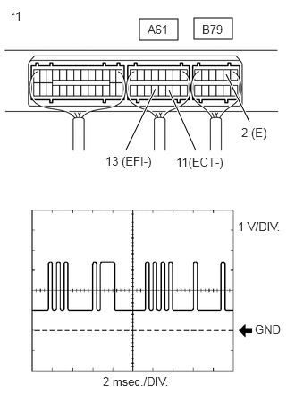
1.INSPECT TCM (ECM - TCM SIGNAL)
a.
1.625,0.219 2.073,0.469
0.448,0.25
2.26,0.208 2.708,0.458
0.448,0.25
2.635,0.865 2.906,1.417
true
1.813,1.031 1.469,1.74
true
1.969,1.052 2.281,1.75
true
2.969,3.75 3.344,3.906
0.375,0.156
10
false
GND
2.771,2.552 3.427,2.76
0.656,0.208
10
false
1 V/DIV.
1.198,4.354 2.813,4.563
1.615,0.208
10
false
2 msec./DIV.
2.052,1.802 2.646,2
0.594,0.198
10
false
11(ECT-)
1.229,1.792 1.865,2.01
0.635,0.219
10
false
13 (EFI-)
1.719,0.26 2.042,0.458
0.323,0.198
10
false
A61
2.354,0.26 2.677,0.458
0.323,0.198
10
false
B79
2.813,1.458 3.229,1.656
0.417,0.198
10
false
2 (E)
0.125,0.104 0.375,0.323
0.25,0.219
10
false
*1
While idling the engine, check the waveform of the TCM connectors using an oscilloscope.
- Standard:
Tester Connection Condition Specified Condition A61-13 (EFI-) - B79-2 (E) Idling Correct waveform appears as shown A61-11 (ECT-) - B79-2 (E) Idling Correct waveform appears as shown
| *1 | Component with harness connected
(TCM) |
b.
1.646,0.177 2.052,0.427
0.406,0.25
2.26,0.177 2.667,0.427
0.406,0.25
2.552,0.865 2.781,1.354
true
1.719,1.052 1.531,1.594
true
1.885,1.052 2.188,1.573
true
2.979,3.76 3.385,3.958
0.406,0.198
10
false
GND
2.76,2.479 3.427,2.667
0.667,0.188
10
false
1 V/DIV.
1.135,4.365 2.198,4.604
1.063,0.24
10
false
2 msec./DIV.
2.719,1.396 3.135,1.604
0.417,0.208
10
false
2 (E)
1.083,1.615 1.719,1.813
0.635,0.198
10
false
14 (EFI+)
1.729,0.229 2.073,0.417
0.344,0.188
10
false
A61
2.344,0.229 2.688,0.417
0.344,0.188
10
false
B79
1.969,1.615 2.708,1.833
0.74,0.219
10
true
12 (ECT+)
0.125,0.115 0.396,0.323
0.271,0.208
10
false
*1
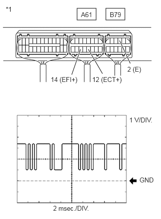
While idling the engine, check the waveform of the TCM connectors using an oscilloscope.
- Standard:
Tester Connection Condition Specified Condition A61-14 (EFI+) - B79-2 (E) Idling Correct waveform appears as shown A61-12 (ECT+) - B79-2 (E) Idling Correct waveform appears as shown
| *1 | Component with harness connected
(TCM) |
- Result:
Proceed to OK NG
OK
REPLACE TCM
Click here @@@@
NG
2.CHECK HARNESS AND CONNECTOR (ECM - TCM)
2.CHECK HARNESS AND CONNECTOR (ECM - TCM)
a.
Disconnect the ECM connector.
b.
Disconnect the TCM connector.
c.
Measure the resistance according to the value(s) in the table below.
- Standard Resistance:
Tester connection Condition Specified Condition A54-24 (ECT-) - A61-11 (ECT-) Always Below 1 Ω A54-25 (ECT+) - A61-12 (ECT+) Always Below 1 Ω A54-30 (EFI-) - A61-13 (EFI-) Always Below 1 Ω A54-31 (EFI+) - A61-14 (EFI+) Always Below 1 Ω A54-24 (ECT-) or A61-11 (ECT-) - Body ground Always 10 kΩ or higher A54-25 (ECT+) or A61-12 (ECT+) - Body ground Always 10 kΩ or higher A54-30 (EFI-) or A61-13 (EFI-) - Body ground Always 10 kΩ or higher A54-31 (EFI+) or A61-14 (EFI+) - Body ground Always 10 kΩ or higher
d.
Reconnect the TCM connector.
e.
Reconnect the ECM connector.
- Result:
Proceed to OK NG
OK
NG
REPAIR OR REPLACE HARNESS OR CONNECTOR