RM2850E
_52
Drivetrain
_073139
A444E AUTOMATIC TRANSMISSION / TRANSAXLE
_0355865
AUTOMATIC TRANSMISSION SYSTEM
J
A444E AUTOMATIC TRANSMISSION / TRANSAXLE AUTOMATIC TRANSMISSION SYSTEM Stop Light Switch Circuit
DESCRIPTION
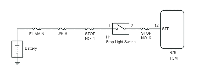
The purpose of this circuit is to prevent the engine from stalling while driving in the lock-up condition and the brakes are suddenly applied.
When the brake pedal is depressed, this switch sends a signal to the TCM. Then the TCM cancels the operation of the lock-up clutch during braking.
WIRING DIAGRAM
0.875,1.625 1.51,1.833
0.635,0.208
10
false
Battery
1.031,1.115 1.688,1.313
0.656,0.198
10
false
FL MAIN
2.042,1.104 2.563,1.302
0.521,0.198
10
false
J/B-B
3,1.115 3.448,1.458
0.448,0.344
10
false
STOP NO. 1
3.813,0.823 4.031,1.021
0.219,0.198
10
false
1
4.615,0.823 4.833,1.021
0.219,0.198
10
false
2
5.448,0.813 5.688,1.01
0.24,0.198
10
false
12
3.74,1.229 4,1.427
0.26,0.198
10
false
H1
3.74,1.396 4.896,1.615
1.156,0.219
10
false
Stop Light Switch
4.979,1.094 5.438,1.438
0.458,0.344
10
false
STOP NO. 6
5.719,0.938 6.135,1.146
0.417,0.208
10
false
STP
5.979,1.781 6.375,1.948
0.396,0.167
10
false
B79
5.979,1.979 6.448,2.146
0.469,0.167
10
false
TCM
CAUTION / NOTICE / HINT
- NOTICE:
-
Inspect the fuses for circuits related to this system before performing the following procedure.
PROCEDURE
1.INSPECT STOP LIGHT SWITCH
a.
Inspect the stop light switch (Click hereVehicle Interior>LIGHTING>STOP LIGHT SWITCH>INSPECTION).
- Result:
Proceed to OK NG
OK
2.CHECK HARNESS AND CONNECTOR (TCM - BATTERY)
NG
REPLACE STOP LIGHT SWITCH
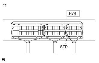
2.CHECK HARNESS AND CONNECTOR (TCM - BATTERY)
a.
2.323,0.354 2.75,0.583
0.427,0.229
2.281,1.51 2.354,1.167
true
0.104,0.104 0.417,0.302
0.313,0.198
10
false
*1
2.396,0.385 2.781,0.573
0.385,0.188
10
false
B79
2.083,1.542 2.469,1.729
0.385,0.188
10
false
STP
Measure the voltage according to the value(s) in the table below.
- Standard Voltage:
Tester Connection Condition Specified Condition B79-12 (STP) - Body ground Brake pedal is depressed 11 to 14 V Brake pedal is depressed Below 1 V
| *1 | Component with harness connected
(TCM) |
- Result:
Proceed to OK NG
OK
PROCEED TO NEXT SUSPECTED AREA SHOWN IN PROBLEM SYMPTOMS TABLE
NG
REPAIR OR REPLACE HARNESS OR CONNECTOR