A444E AUTOMATIC TRANSMISSION / TRANSAXLE AUTOMATIC TRANSMISSION UNIT DISASSEMBLY
PROCEDURE

 35104B
1.REMOVE NO.1 BREATHER PLUG (ATM)
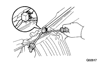
Using 2 screwdrivers, remove the No.1 breather plug(ATM) and breather tube together.
Remove the clip and No.1 breather plug(ATM) from the breather tube.
Remove the O-ring from the No.1 breather plug(ATM).
35573
2.REMOVE TRANSMISSION CONTROL SHAFT LEVER LH
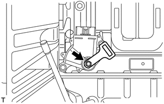
Remove the 2 nuts and transmission control shaft lever LH.
84540
3.REMOVE PARK/NEUTRAL POSITION SWITCH ASSEMBLY
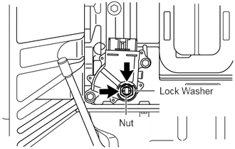
Using a screwdriver, pry out the lock washer.
Remove the lock nut and lock washer.
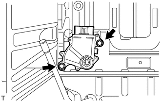
Remove the 2 bolts and park/neutral position switch.
89429A
4.REMOVE TEMPERATURE SENSOR
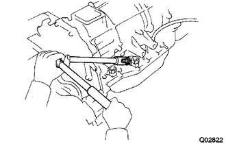
Remove the temperature sensor from the oil cooler tube union (front side).
32921C
5.REMOVE OIL COOLER TUBE UNION
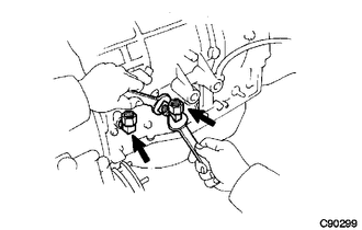
Loosen the lock nut and remove the oil cooler tube union (front side).
Remove the O-ring from the oil cooler tube union (front side).
Loosen the lock nut and remove the oil cooler tube union (rear side).
Remove the O-ring from the oil cooler tube union (rear side).
35111
6.REMOVE AUTOMATIC TRANSMISSION HOUSING
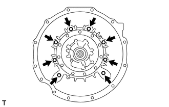
Remove the 8 bolts and automatic transmission housing.
Remove the automatic transmission case O-ring.
89413B
7.REMOVE TRANSMISSION REVOLUTION SENSOR
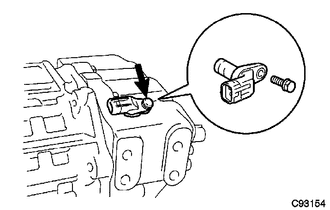
Remove the bolt and the transmission revolution sensor.
83181G
8.REMOVE SPEEDOMETER SENSOR
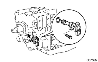
Remove the bolt and the speedometer sensor.
Remove the O-ring from the speedometer sensor.
35106
9.REMOVE AUTOMATIC TRANSMISSION OIL PAN SUB-ASSEMBLY
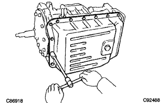
Remove the 20 bolts.
- NOTICE:
-
Do not turn the transmission over as this will contaminate the valve body with foreign matter located at the bottom of the pan.
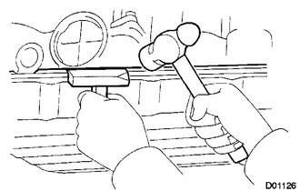
Insert oil pan seal cutter between the transmission case and oil pan. Cut through the seal and remove the oil pan.
- NOTICE:
-
Be careful not to damage the oil pan flange.
35394
10.REMOVE TRANSMISSION OIL CLEANER MAGNET
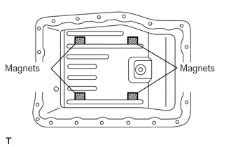
Remove the 4 transmission oil cleaner magnets from the oil pan.
- HINT:
-
Confirm the postion of the magnets.
35330
11.REMOVE VALVE BODY OIL STRAINER ASSEMBLY
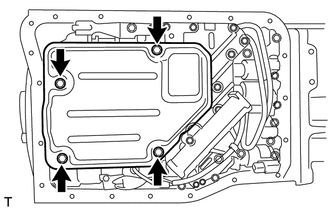
Remove the 4 bolts and oil strainer from the transmission valve body assembly.
35261A
12.REMOVE THROTTLE PRESSURE ACCUMULATOR CYLINDER
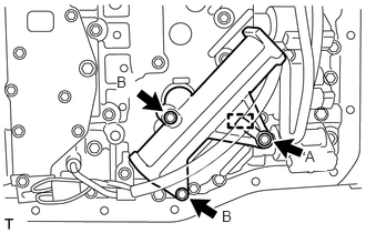
Remove the bolt and clamp.(A)
Remove the 2 bolts and throttle pressure accumulator cylinder.(B)
Remove the center support apply gasket.
82125J
13.REMOVE TRANSMISSION WIRE
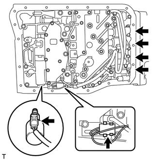
Disconnect the 5 connectors from the solenoid valves.(A)
Disconnect the ATF temperature sensor's clamp.(B)
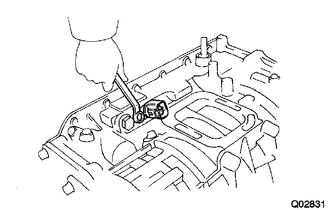
Remove the bolt and pull out the transmission wire.
Remove the O-ring from the transmission wire.
35410
14.REMOVE TRANSMISSION VALVE BODY ASSEMBLY
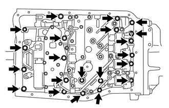
Remove the 21 bolts and transmission valve body assembly.
- NOTICE:
-
Confirm the position of the bolts.
35893
15.REMOVE CENTER SUPPORT APPLY GASKET
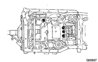
Remove the 4 center support apply gaskets.
35425A
16.REMOVE C-2 ACCUMULATOR PISTON
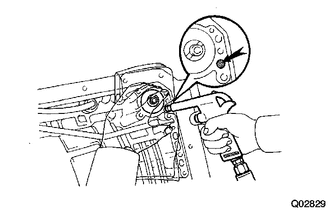
While holding the C-2 accumulator piston, blowing compressed air into the oil hole to remove the C-2 accumulator piston and the spring.
- NOTICE:
-
Take care as the oil and piston may jump out.
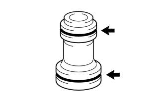
Using a screwdriver with its tip wrapped with tape, remove the 2 O-rings.
17.REMOVE NO.2 ACCUMULATOR PISTON
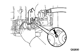
While holding the C-2 accumulator piston, blowing compressed air into the oil hole to remove the No.2 accumulator piston and the spring.
- NOTICE:
-
Take care as the oil and piston may jump out.
Using a screwdriver with its tip wrapped with tape, remove the 2 O-rings.
34421
18.REMOVE OVERDRIVE BRAKE ACCUMULATOR PISTON
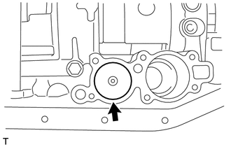
Remove the overdrive brake accumulator piston from the transmission case.
Using a screwdriver with its tip wrapped with tape, remove the 2 O-rings.
19.REMOVE OIL PUMP ASSEMBLY
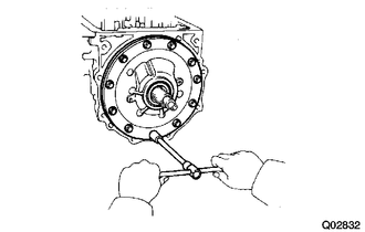
Loosen the 11 bolts equally and remove them from the transmission case.
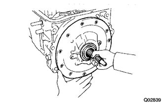
Remove the oil pump assembly from the transmission case.
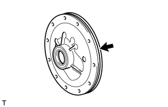
Remove the front oil pump body O-ring from the oil pump assembly.
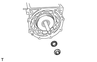
Remove the thrust needle roller bearing and thrust bearing race from the overdrive planetary gear and overdrive direct clutch assembly.
20.INSPECT OVERDRIVE DIRECT CLUTCH
21.REMOVE OVERDRIVE PLANETARY GEAR AND OVERDRIVE DIRECT CLUTCH ASSEMBLY
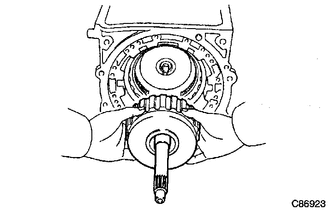
Remove the overdrive planetary gear and overdrive direct clutch assembly.
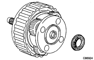
Remove the thrust needle roller bearing from the overdrive planetary gear and overdrive direct clutch assembly.
35677B
22.REMOVE OVERDRIVE BRAKE CLUTCH DISC
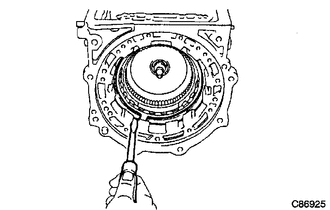
Using a screwdriver, remove the overdrive brake flange hole snap ring from the transmission case.
- NOTICE:
-
Do not damage the transmission case.
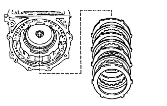
Remove the No.1 overdrive brake flange, 3 overdrive brake clutch discs and 3 overdrive brake plates from the transmission case.
34625
23.INSPECT NO.1 OVERDRIVE BRAKE FLANGE
35677B
24.INSPECT OVERDRIVE BRAKE CLUTCH DISC
34731
25.REMOVE OVERDRIVE PLANETARY RING GEAR
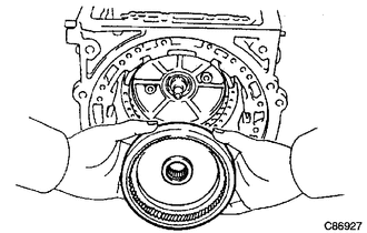
Remove the overdrive planetary ring gear from the transmission case.
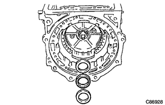
Remove the thrust needle roller bearing and 2 thrust bearing races from the transmission case.
26.REMOVE OVERDRIVE SUPPORT ASSEMBLY
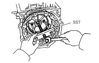
Using a SST, remove the overdrive support assembly.
- SST
- 09350-36010 (09350-06140)
34622
27.INSPECT OVERDRIVE BRAKE PISTON
34603
28.REMOVE OVERDRIVE BRAKE RETURN SPRING SUB-ASSEMBLY
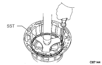
Using a SST, press the overdrive brake return spring sub-assembly, and then remove the overdrive brake return spring hole snap ring.
- SST
- 09350-36010 (09350-06020)
- NOTICE:
-
Step the press at the position where the spring sheet face is 1 to 2 mm lower than the snap ring.
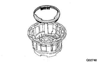
Remove the overdrive brake return spring sub-assembly.
34622
29.REMOVE OVERDRIVE BRAKE PISTON
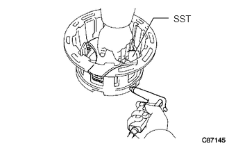
Using a SST, press the piston equally, while blowing compressed air into the oil hole, and then remove the overdrive brake piston.
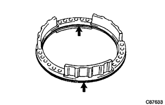
Using a screwdriver with its tip wrapped with tape, remove the 2 O-rings from the overdrive brake piston.
35617A
30.REMOVE OVERDRIVE CLUTCH DRUM OIL SEAL RING
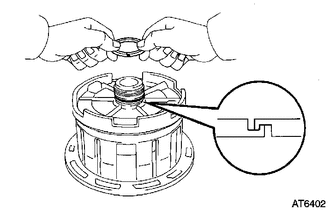
Remove the 2 overdrive clutch drum oil seal rings from the overdrive case sub-assembly.
34101B
31.REMOVE OVERDRIVE CASE O-RING
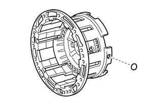
Remove the 3 overdrive case O-rings from the overdrive case sub-assembly.
35785A
32.REMOVE OVERDRIVE CASE RING RETAINER
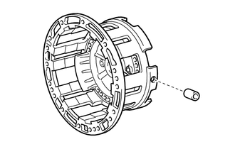
Remove the 3 overdrive case ring retainers from the overdrive case sub-assembly.
34101
33.INSPECT OVERDRIVE CASE SUB-ASSEMBLY
34.INSPECT FRONT CLUTCH ASSEMBLY
35.REMOVE FRONT CLUTCH ASSEMBLY
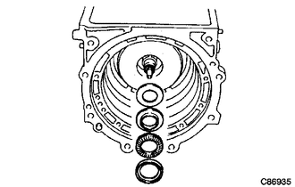
Remove the thrust needle roller bearing and 3 thrust bearing races from front clutch assembly.
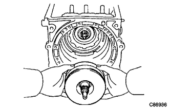
Remove the front clutch assembly from the rear clutch assembly.
36.REMOVE REAR CLUTCH ASSEMBLY
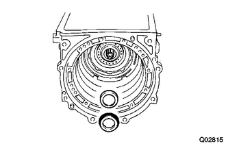
Remove the thrust needle roller bearing and thrust bearing race from rear clutch assembly.
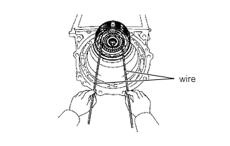
Using 2 wires, remove the rear clutch assembly from the center support assembly.
37.REMOVE CENTER SUPPORT ASSEMBLY
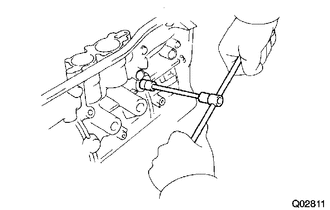
Remove the 3 center support set overdrive case & transmission case set bolts.
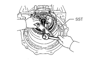
Using a SST, remove the center support assembly.
- SST
- 09350-36010 (09350-06140)
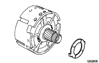
Remove the center support washer from the center support assembly.
35108R
38.REMOVE AUTOMATIC TRANSMISSION EXTENSION HOUSING OIL SEAL
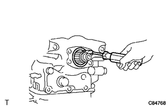
Using a screwdriver with its tip wrapped with tape, remove the automatic transmission extension housing oil seal.
35181
39.REMOVE EXTENSION (ATM) HOUSING SUB-ASSEMBLY
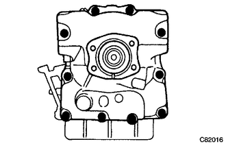
Using a plastic hammer, remove the 10 bolts and extension (ATM) housing sub-assembly.
Remove the extension (ATM) housing gasket from the automatic transmission case.
35556
40.REMOVE PARKING LOCK PAWL SHAFT
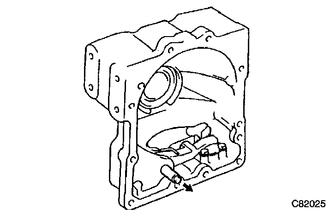
Remove the parking lock pawl shaft from the extension (ATM) housing sub-assembly.
35557
41.REMOVE PARKING LOCK PAWL
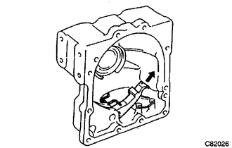
Remove the parking lock pawl, parking lock pawl shaft washer and parking lock pawl shaft spring from the extension (ATM) housing sub-assembly.
35595
42.REMOVE PARKING LOCK PAWL BRACKET
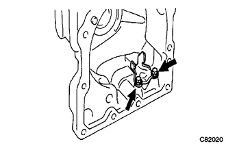
Remove the 2 bolts and parking lock pawl bracket from the extension (ATM) housing sub-assembly.
35073D
43.REMOVE OUTPUT SHAFT REAR RADIAL BALL BEARING
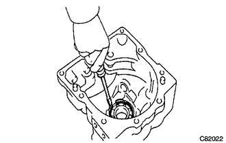
Using a screwdriver, remove the spacer from the extension (ATM) housing sub-assembly.
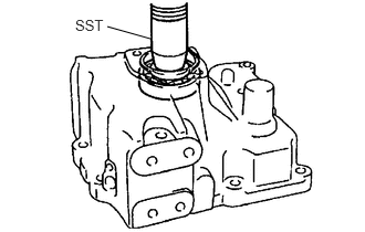
Using a SST and press, remove the output shaft rear radial ball bearing.
- SST
- 09350-36010 (09350-06070)
33481S
44.REMOVE SPEEDOMETER DRIVE (ATM) GEAR
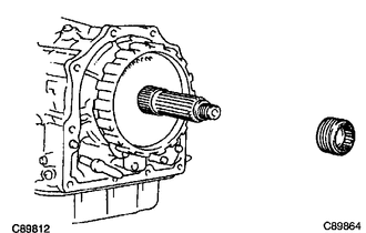
Remove the speedometer driven (ATM) gear.
35469J
45.REMOVE PARKING LOCK GEAR SPACER
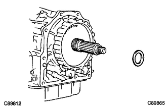
Remove the parking lock gear spacer.
35733
46.REMOVE PARKING LOCK GEAR
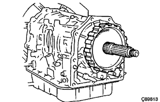
Remove the parking lock gear.
47.REMOVE PLANETARY GEAR ASSEMBLY AND OUTPUT SHAFT
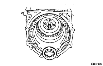
Remove the No.1 planetary carrier thrust washer.
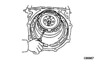
Using a screwdriver, remove the front planetary ring gear hole snap ring.
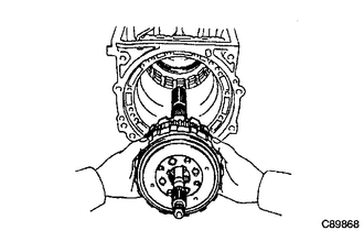
Remove the planetary gear assembly & output shaft from the automatic transmission case.
35720
48.REMOVE FRONT PLANETARY GEAR ASSEMBLY
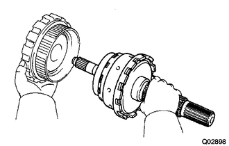
Remove the front planetary gear assembly.
35737A
49.REMOVE NO.1 PLANETARY CARRIER THRUST WASHER
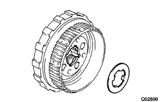
Remove the No.1 planetary carrier thrust washer from the front planetary gear assembly.
35790A
50.INSPECT 1 WAY CLUTCH ASSEMBLY
35790A
51.REMOVE 1 WAY CLUTCH ASSEMBLY
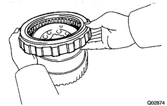
Remove the 1 way clutch assembly from the front planetary gear assembly.
35720
52.INSPECT FRONT PLANETARY GEAR ASSEMBLY
35073
53.REMOVE OUTPUT SHAFT SUB-ASSEMBLY
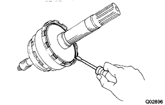
Using a screwdriver, remove the output shaft hole snap ring.
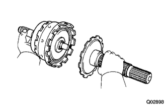
Remove the output shaft assembly from the rear planetary gear assembly.
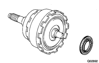
Remove the thrust needle roller bearing from the rear planetary gear assembly.
35073
54.INSPECT OUTPUT SHAFT SUB-ASSEMBLY
35760
55.REMOVE REAR PLANETARY GEAR ASSEMBLY
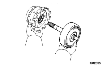
Remove the rear planetary gear assembly.
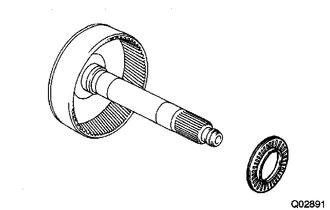
Remove the thrust needle roller bearing.
35748B
56.REMOVE INTERMEDIATE SHAFT OIL SEAL RING
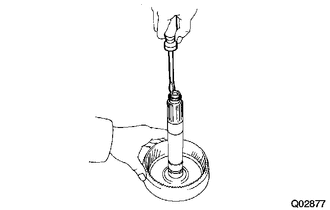
Using a screwdriver, remove the intermediate shaft oil seal ring.
35713
57.REMOVE INTERMEDIATE SHAFT
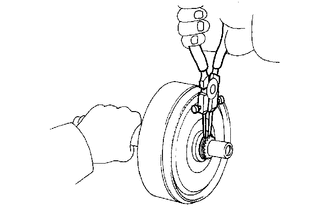
Using a No.1 snap ring expander, remove the snap ring.
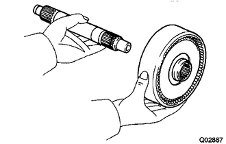
Remove the intermediate shaft.
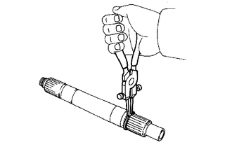
Using a No.1 snap ring expander, remove the snap ring.
35719A
58.REMOVE REAR PLANETARY SUN GEAR
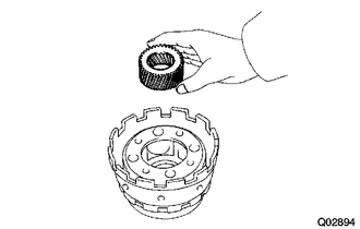
Remove the rear planetary sun gear.
35762
59.REMOVE REAR PLANETARY RING GEAR FLANGE
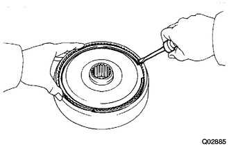
Using a screwdriver, remove the snap ring.
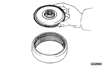
Remove the rear planetary ring gear flange.
35743
60.REMOVE FRONT PLANETARY RING GEAR
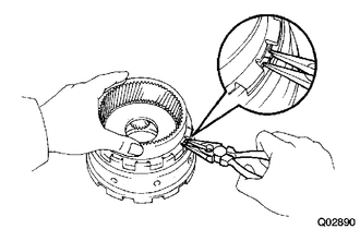
Using a needle nose pliers, shorten the snap ring and remove the front planetary ring gear.
Remove the snap ring.
35738
61.REMOVE NO.2 PLANETARY CARRIER THRUST WASHER
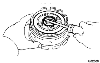
Using a screwdriver, remove the No.2 planetary carrier thrust washer from rear planetary gear assembly.
35703A
62.REMOVE REAR PLANETARY CARRIER O-RING
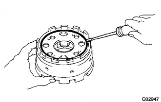
Using a screwdriver, remove the rear planetary carrier O-ring from rear planetary gear assembly.
35760
63.INSPECT REAR PLANETARY GEAR ASSEMBLY
35623H
64.INSPECT 1ST & REVERSE BRAKE PISTON
35677A
65.REMOVE 1ST & REVERSE BRAKE CLUTCH DISC
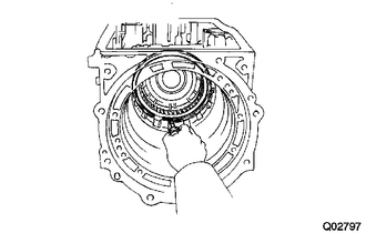
Using a screwdriver, remove the snap ring from the automatic transmission case.
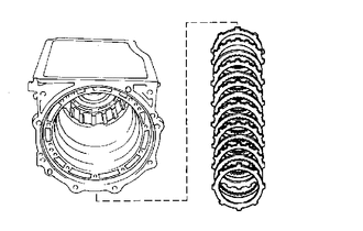
Remove the 1st & reverse brake flange, 6 1st & reverse brake clutch discs, 6 1st & reverse brake plates, and brake cushion plate from the automatic transmission case.
35677A
66.INSPECT 1ST & REVERSE BRAKE CLUTCH DISC
35623H
67.REMOVE 1ST & REVERSE BRAKE PISTON
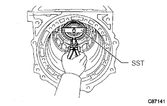
Using a SST, remove the brake piston return spring hole snap ring.
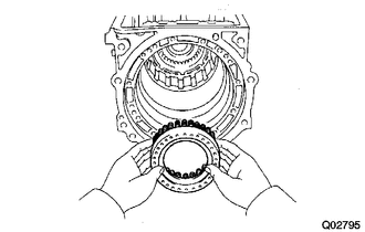
Remove the 1st & reverse brake return spring sub-assembly.
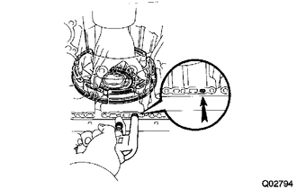
While blowing compressed air into the oil hole, remove the 1st & reverse brake piston.
- NOTICE:
-
Take care as the oil and piston may jump out.
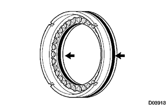
Using a screwdriver with its tip wrapped with tape, remove the 2 O-rings.
35068
68.INSPECT 1ST & REVERSE BRAKE RETURN SPRING SUB-ASSEMBLY
35073C
69.REMOVE OUTPUT SHAFT FRONT RADIAL BALL BEARING
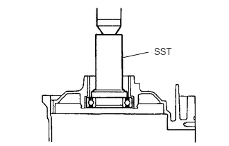
Using a SST and press, remove the output shaft rear radial ball bearing.
35424C
70.REMOVE C-1 ACCUMULATOR PISTON
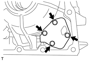
Remove the 4 bolts and front clutch accumulator cover.
Remove the No.1 front clutch accumulator gasket, front clutch accumulator plate and No.2 front clutch accumulator gasket.
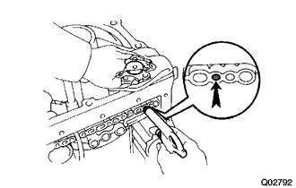
While blowing compressed air into the oil hole, remove the C-1 accumulator piston.
Using a screwdriver with its tip wrapped with tape, remove the 2 O-rings.
35505
71.REMOVE MANUAL VALVE LEVER SUB-ASSEMBLY
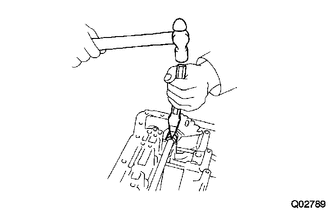
Using a chisel and a hammer, cut off the manual valve lever shaft spacer.
Remove the manual valve lever shaft spacer.
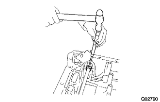
Using a pin punch (f 3mm) and a hammer, remove the manual valve lever spring pin.
- HINT:
-
Put a piece of cloth underneath to prevent from losing the pin.
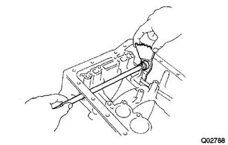
Disconnect the manual valve lever shaft, removed the manual valve lever sub-assembly.
35501
72.REMOVE PARKING LOCK ROD SUB-ASSEMBLY
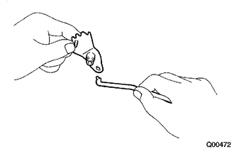
Disconnect the parking lock rod sub-assembly from the manual valve lever.
35506F
73.REMOVE MANUAL VALVE LEVER SHAFT OIL SEAL
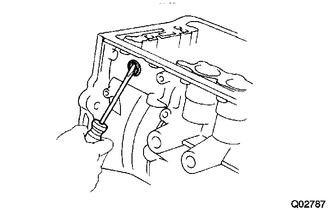
Using a screwdriver, remove the 2 manual valve shaft oil seals from the automatic transmission case.