A444E AUTOMATIC TRANSMISSION / TRANSAXLE AUTOMATIC TRANSMISSION UNIT REASSEMBLY
PROCEDURE

 1. BEARING POSITION
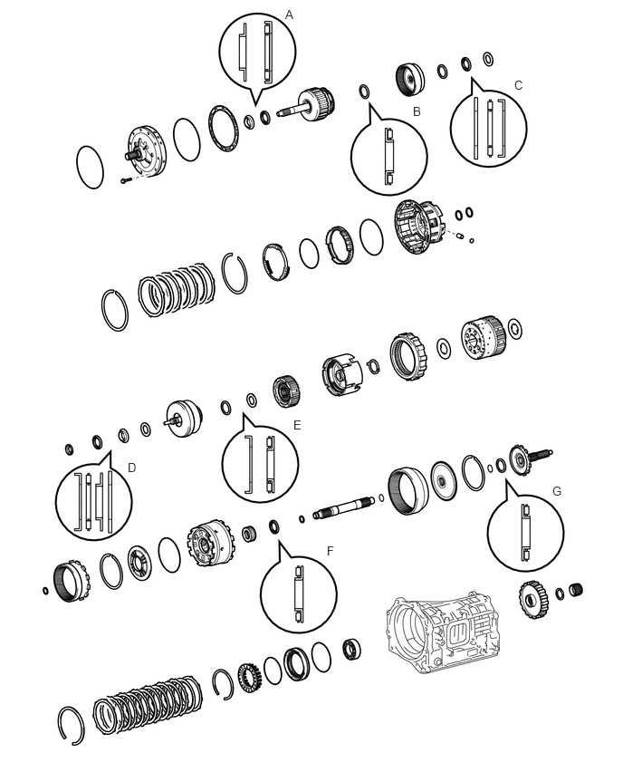
| Mark | Front Race Diameter
Inside/Outside |
Thrust Bearing Diameter
Inside/Outside |
Rear Race Diameter
Inside/Outside |
RR Race Diameter
Inside/Outside |
|---|---|---|---|---|
| A | 28.3 mm (1.114 in.)/43.0 mm (1.692 in.) | 28.5 mm (1.122 in.)/48.0 mm (1.890 in.) | - | - |
| 27.85 mm (1.097 in.)/43.0 mm (1.692 in.) | ||||
| 27.05 mm (1.065 in.)/43.0 mm (1.692 in.) | ||||
| B | - | 23.15 mm (0.911 in.)/42.0 mm (1.654 in.) | - | - |
| C | 34.6 mm (1.362 in.)/58.2 mm (2.291 in.) | 34.65 mm (1.403 in.)/58.4 mm (2.299 in.) | 37.0 mm (1.456 in.)/58.5 mm (2.303 in.) | - |
| D | 37.0 mm (1.457 in.)/51.95 mm (2.045 in.) | 34.65 mm (1.364 in.)/52.0 mm (2.047 in.) | 32.75 mm (1.289 in.)/50.4 mm (1.984 in.) | 33.0 mm (1.299 in.)/50.4 mm (1.984 in.) |
| E | 37.0 mm (1.457 in.)/51.95 mm (2.045 in.) | 32.75 mm (1.289 in.)/52.0 mm (2.047 in.) | - | - |
| F | - | 32.75 mm (1.289 in.)/53.2 mm (2.095 in.) | - | - |
| G | - | 32.75 mm (1.289 in.)/53.2 mm (2.095 in.) | - | - |
35506F
2.INSTALL MANUAL VALVE LEVER SHAFT OIL SEAL
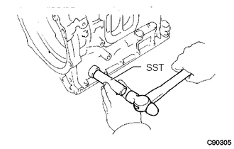
Coat 2 new manual valve shaft oil seals with ATF, and install them to the automatic transmission case using a SST.
- SST
- 09350-36010 (09350-06150)
Coat the oil seal lips with MP grease.
35501
3.INSTALL PARKING LOCK ROD SUB-ASSEMBLY
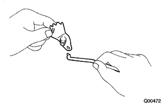
Install the parking lock rod to the manual valve lever.
35505
4.INSTALL MANUAL VALVE LEVER SUB-ASSEMBLY
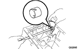
Install a new spacer to the manual valve lever.
Install the manual valve lever shaft to the transmission case through the manual valve lever.
Using a hammer, drive in a new spring pin.
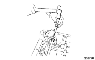
Align the manual valve lever indentation with the spacer hole, and stake them together with the punch (3mm).
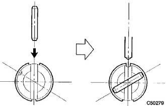
Turn the spacer and lever shaft in order to align the small hole of the spacer chunking point mark with chunking point mark of the lever shaft. Over the small hole of the spacer, chunk that the spacer does not turn.
35424C
5.INSTALL C-1 ACCUMULATOR PISTON
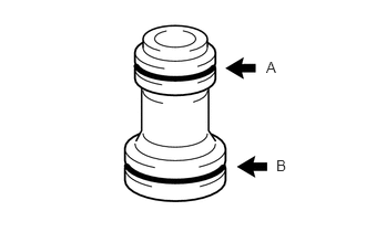
Coat 2 new O-rings with ATF, and install them to the C1 accumulator piston.
- NOTICE:
-
Be careful not to damage the O-rings.
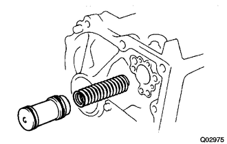
Coat the C-1 accumulator piston and spring with ATF, and install them to the automatic transmission case.
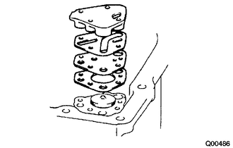
Install the new No.2 front clutch accumulator gasket, front clutch accumulator plate, new No.1 front clutch accumulator gasket to the automatic transmission case.
Install the front clutch accumulator cover with the 4 bolts.
- Torque:
8.0 N*m (82 kgf*cm, 71 in.*lbf)
35073C
6.INSTALL OUTPUT SHAFT FRONT RADIAL BALL BEARING
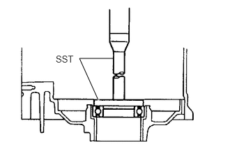
Using a SST and a press, install the new output shaft front radial ball bearing to the automatic transmission case.
35623H
7.INSTALL 1ST & REVERSE BRAKE PISTON
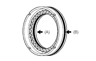
Coat 2 new O-rings with ATF, and install them to the 1st & reverse brake piston.
- NOTICE:
-
Be careful not to damage the O-rings.
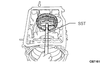
Coat the 1st & reverse brake piston with ATF, and install them to the automatic transmission case.
- SST
- 09350-36010 (09350-06020, 09350-06030, 09350-06050)
09350-30020 (09350-07070)
- NOTICE:
-
Be careful not to damage the O-rings.
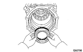
Install the 1st & reverse brake return spring sub-assembly to the 1st & reverse brake piston.
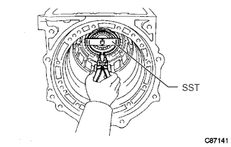
Using SST, install the snap ring.
- SST
- 09350-30020 (09350-07070)
35677A
8.INSTALL 1ST & REVERSE BRAKE CLUTCH DISC
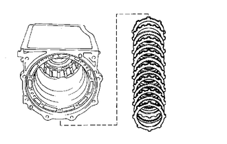
Install the 1st & reverse brake flange, 6 1st & reverse brake clutch discs, 6 1st & reverse brake plates, and brake cushion plate to the automatic transmission case.
- HINT:
-
When assembling new discs, soak them in ATF for at least 2 hours.
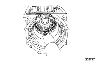
Using a screwdriver, install the snap ring.
9.INSPECT PISTON STROKE OF 1ST & REVERSE BRAKE
35703A
10.INSTALL REAR PLANETARY CARRIER O-RING
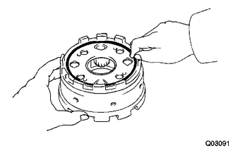
Coat a new rear planetary carrier O-ring with ATF, and then install to the rear planetary gear assembly.
35738
11.INSTALL NO.2 PLANETARY CARRIER THRUST WASHER
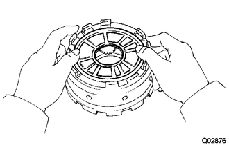
Coat the No.2 planetary carrier thrust washer with petroleum jelly, install and them to the rear planetary gear assembly.
35743
12.INSTALL FRONT PLANETARY RING GEAR
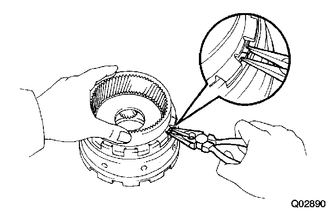
Install the snap ring to the rear planetary gear assembly.
Using a needle nose pliers, shorten the snap ring and install the front planetary ring gear to the rear planetary gear assembly.
35762
13.INSTALL REAR PLANETARY RING GEAR FLANGE
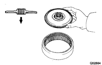
Install the rear planetary ring gear flange to the rear planetary ring gear.
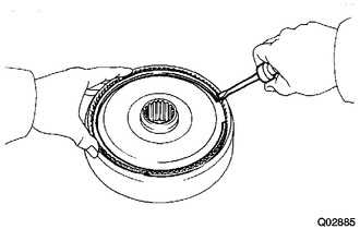
Using a screwdriver, install the snap ring to the rear planetary ring gear.
35719A
14.INSTALL REAR PLANETARY SUN GEAR
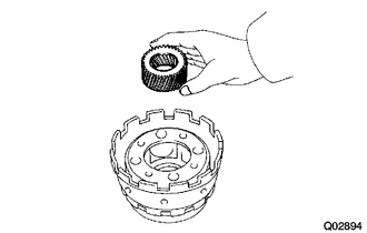
Install the rear planetary sun gear.
35713
15.INSTALL INTERMEDIATE SHAFT
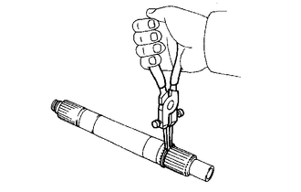
Using a No.1 snap ring expander, install the snap ring to the intermediate shaft.
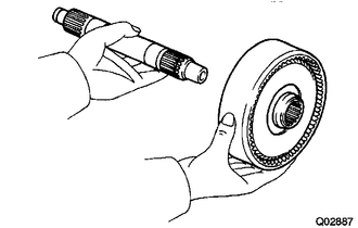
Install the intermediate shaft to the rear planetary ring gear assembly.
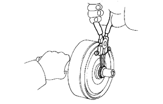
Using a No.1 snap ring expander, install the snap ring.
35748B
16.INSTALL INTERMEDIATE SHAFT OIL SEAL RING
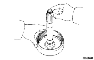
Coat a new intermediate shaft oil seal ring with ATF, and install it to the rear planetary ring gear assembly.
35760
17.INSTALL REAR PLANETARY GEAR ASSEMBLY
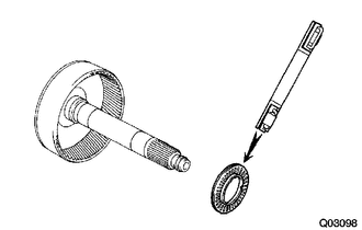
Coat a thrust needle roller bearing with petroleum jelly, and install it to the rear planetary ring gear assembly.
| Inside | Outside | |
|---|---|---|
| Bearing | 32.75 mm (1.289 in.) | 53.2 mm (2.095 in.) |
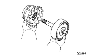
Install the rear planetary gear assembly to the rear planetary ring gear assembly.
- NOTICE:
-
Do not drop the rear planetary sun gear.
35073
18.INSTALL OUTPUT SHAFT SUB-ASSEMBLY
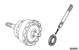
Coat a thrust needle roller bearing with petroleum jelly, and install it to the rear planetary gear assembly.
| Inside | Outside | |
|---|---|---|
| Bearing | 32.75 mm (1.289 in.) | 53.2 mm (2.095 in.) |
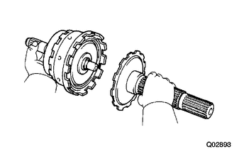
Install the output shaft sub-assembly.
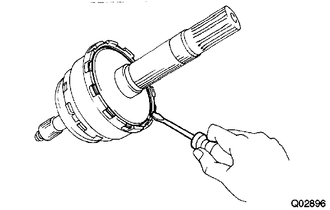
Using a screwdriver, install the snap ring.
35790A
19.INSTALL 1 WAY CLUTCH ASSEMBLY
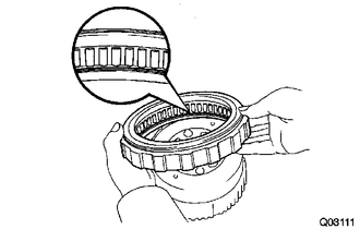
Install the 1 way clutch assembly to the front planetary gear assembly.
35737A
20.INSTALL NO.1 PLANETARY CARRIER THRUST WASHER
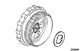
Coat a No.1 planetary carrier thrust washer with petroleum jelly, and install it to the front planetary gear assembly.
35720
21.INSTALL FRONT PLANETARY GEAR ASSEMBLY
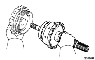
Install the front planetary gear assembly.
22.INSTALL PLANETARY GEAR ASSEMBLY AND OUTPUT SHAFT
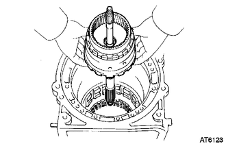
Install the planetary gear assembly & output shaft to the automatic transmission case.
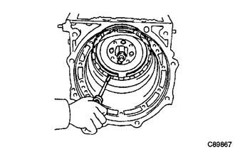
Using a screwdriver, install the snap ring.
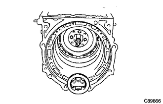
Install the No.1 planetary carrier thrust washer to the front planetary gear assembly.
35733
23.INSTALL PARKING LOCK GEAR
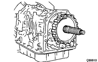
Install the parking lock gear to the output shaft.
35469J
24.INSTALL PARKING LOCK GEAR SPACER
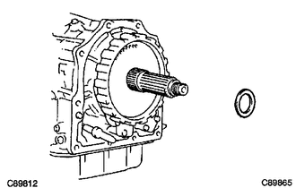
Install the parking lock gear spacer to the output shaft.
33481S
25.INSTALL SPEEDOMETER DRIVE (ATM) GEAR
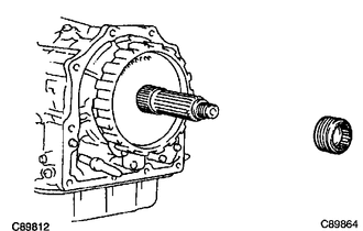
Install the speedometer driven (ATM) gear to the output shaft.
35073D
26.INSTALL OUTPUT SHAFT REAR RADIAL BALL BEARING
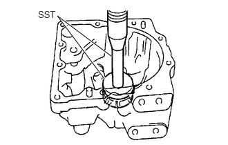
Using a SST and press, install the output shaft rear radial ball bearing.
- SST
- 09350-36010 (09350-06080, 09350-06150)
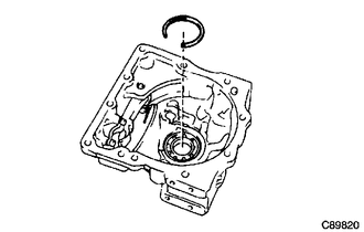
Install the spacer to the the extension (ATM) housing sub-assembly.
35595
27.INSTALL PARKING LOCK PAWL BRACKET
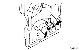
Install the parking lock pawl bracket to the extension (ATM) housing sub-assembly.
Temporarily install the 2 bolts.
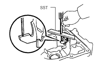
Using a vernier caliper, measure the distance between the top of SST and extension (ATM) housing sub-assembly. If the distance is not as specified, check for an improper installation.
- SST
- 09350-36010 (09350-06100)
Install the parking lock pawl bracket with the 2 bolts.
- Torque:
19 N*m (194 kgf*cm, 14 ft.*lbf)
35557
28.INSTALL PARKING LOCK PAWL
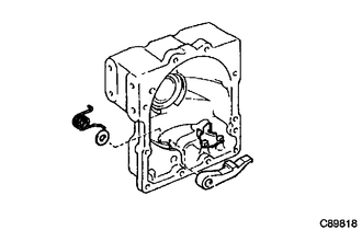
Install the parking lock pawl , parking lock pawl shaft washer and parking lock pawl shaft spring to the extension (ATM) housing sub-assembly.
35556
29.INSTALL PARKING LOCK PAWL SHAFT
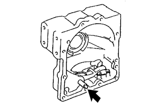
Install the parking lock pawl shaft to the extension (ATM) housing sub-assembly.
35181
30.INSTALL EXTENSION (ATM) HOUSING SUB-ASSEMBLY
Install the new extension (ATM) housing gasket to the automatic transmission case.
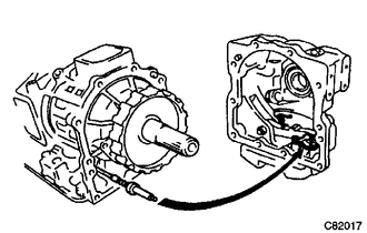
Install the extension (ATM) housing to the automatic transmission case.
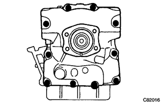
Install the extension (ATM) housing sub-assembly with 10 bolts.
- Torque:
37 N*m (377 kgf*cm, 27 ft.*lbf)
35108R
31.INSTALL AUTOMATIC TRANSMISSION EXTENSION HOUSING OIL SEAL
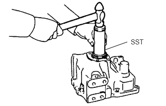
Using SST and a hammer, install a new automatic transmission extension housing oil seal.
- SST
- 09350-36010 (09350-06040)
Coat the oil seal lip with MP grease.
32.INSPECT CENTER SUPPORT ASSEMBLY
33.INSTALL CENTER SUPPORT ASSEMBLY
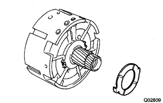
Install the center support washer to the center support assembly.
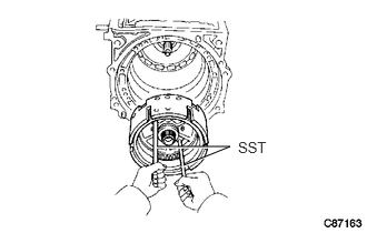
Using a SST, align the center support assembly with eash bolt hole and oil hole.
- SST
- 09350-36010 (09350-06140)
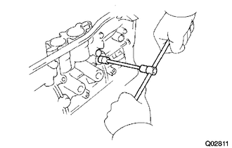
Apply adhesive to 2 or 3 threads of the 3 bolts.
- Torque:
25 N*m (255 kgf*cm, 18 ft.*lbf)
Install the center support assembly with the 3 bolts.
34.INSTALL REAR CLUTCH ASSEMBLY
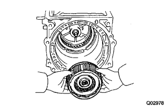
Install the rear clutch assembly to the center support assembly.
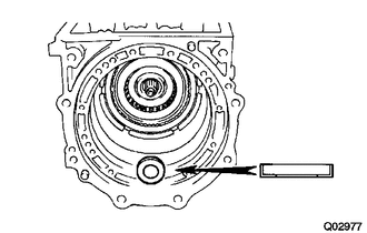
Coat the thrust bearing race with petroleum jelly, and install them to the rear clutch assembly.
- HINT:
Inside Outside Race 37.0 mm (1.457 in.) 51.95 mm (2.045 in.) Bearing 32.75 mm (1.289 in.) 52.0 mm (2.047 in.)
35.INSTALL FRONT CLUTCH ASSEMBLY
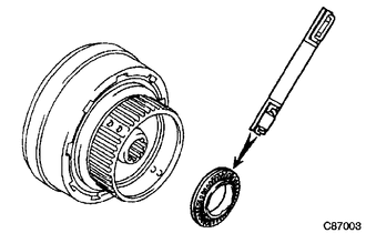
Coat a thrust needle roller bearing with petroleum jelly, and install them to the front clutch assembly.
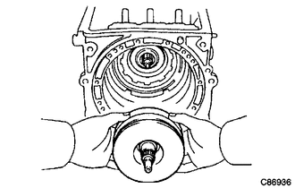
Install the front clutch assembly to the rear clutch assembly.
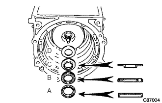
Coat a thrust needle roller bearing,3 thrust bearing race with petroleum jelly,and install them to the front clutch assembly.
- HINT:
Inside Outside A (Race) 37.0 mm (1.457 in.) 51.95 mm (2.045 in.) B (Bearing) 34.65 mm (1.364 in.) 52.0 mm (2.047 in.) C (Race) 32.75 mm (1.289 in.) 50.4 mm (1.984 in.) D (Race) 33.0 mm (1.299 in.) 50.4 mm (1.984 in.)
36.INSPECT FRONT CLUTCH ASSEMBLY
35785A
37.INSTALL OVERDRIVE CASE RING RETAINER
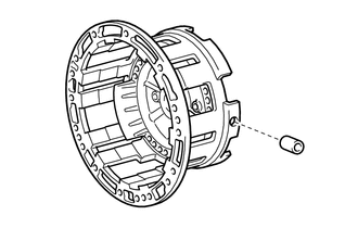
Coat 3 new overdrive case ring retainers with ATF, and install them to the overdrive case sub-assembly.
34101B
38.INSTALL OVERDRIVE CASE O-RING
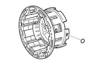
Coat 3 new 3 overdrive case O-rings with ATF, and install them to the overdrive case sub-assembly.
35617A
39.INSTALL OVERDRIVE CLUTCH DRUM OIL SEAL RING
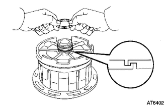
Install the 2 overdrive clutch drum oil seal rings to the overdrive case sub-assembly.
- NOTICE:
-
Do not expand the oil seal ring ends excessively.
34622
40.INSTALL OVERDRIVE BRAKE PISTON
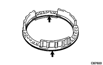
Coat 2 new overdrive brake piston O-rings with ATF, and install them to the overdrive brake piston.
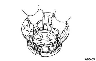
Install the overdrive brake piston to the overdrive case sub-assembly.
- NOTICE:
-
Do not damage the overdrive brake piston O-ring.
34603
41.INSTALL OVERDRIVE BRAKE RETURN SPRING SUB-ASSEMBLY
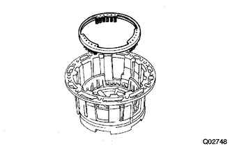
Install the overdrive brake return spring sub-assembly to the overdrive case sub-assembly.
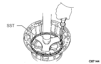
Using a SST and press, shorten the spring, and then install the snap ring.
- SST
- 09350-36010 (09350-06020)
- NOTICE:
-
Stop the press at the position where the spring sheet face is 1 to 2 mm lower than the snap ring.
42.INSTALL OVERDRIVE SUPPORT ASSEMBLY
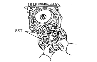
Using a SST, align of the overdrive support oil holes with the transmission case 3 bolt holes.
- SST
- 09350-36010 (09350-06140)
Install the overdrive support assembly to the transmission case.
43.INSPECT INPUT SHAFT ENDPLAY
34731
44.INSTALL OVERDRIVE PLANETARY RING GEAR
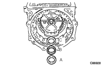
Coat a thrust needle roller bearing, 2 thrust bearing races with petroleum jelly, and install them to the overdrive support assembly.
- HINT:
Inside Outside A (Race) 34.6 mm (1.362 in.) 58.2 mm (2.291 in.) B (Bearing) 34.65 mm (1.403 in.) 58.4 mm (2.299 in.) C (Race) 37.0 mm (1.456 in.) 58.5 mm (2.303 in.)
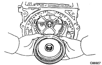
Install the overdrive planetary ring gear to the transmission case.
35677B
45.INSTALL OVERDRIVE BRAKE CLUTCH DISC
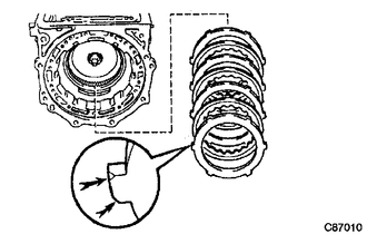
Coat the No.1 overdrive brake flange, 3 overdrive brake clutch discs and 3 overdrive brake plates with ATF, and install them to the transmission case.
- HINT:
-
Before assembling new clutch discs, soak them in ATF for more than 2 hours.
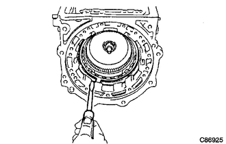
Using a screwdriver, install the overdrive brake flange hole snap ring to the transmission case.
46.INSTALL OVERDRIVE PLANETARY GEAR AND OVERDRIVE DIRECT CLUTCH ASSEMBLY
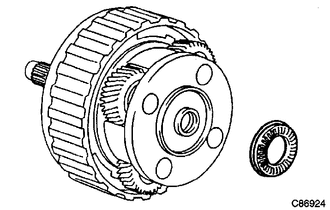
Coat a thrust needle roller bearing with petroleum jelly, and install them to the overdrive planetary gear & overdrive direct clutch assembly.
| Inside | Outside | |
|---|---|---|
| Bearing | 23.15 mm (0.911 in.) | 42.0 mm (1.654 in.) |
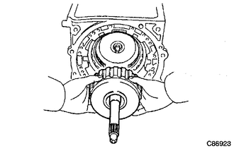
Install the overdrive planetary gear & overdrive direct clutch assembly to the transmission case.
47.INSPECT OVERDRIVE DIRECT CLUTCH
48.INSPECT PISTON STROKE OF OVERDRIVE DIRECT CLUTCH
49.INSTALL OIL PUMP ASSEMBLY
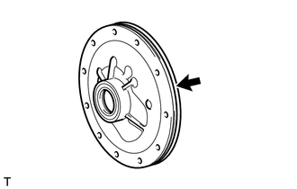
Coat a new front oil pump body O-ring with ATF, and install them to the oil pump assembly.
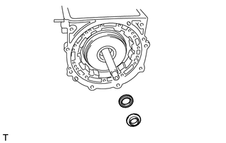
Coat a thrust needle roller bearing and thrust bearing race with petroleum jelly, and install them to the oil pump assembly (rear side).
| Inside | Outside | |
|---|---|---|
| Race | 28.3 mm (1.114 in.) | 43.0 mm (1.692 in.) |
| 27.85 mm (1.097 in.) | ||
| 27.05 mm (1.065 in.) | ||
| Bearing | 28.5 mm (1.122 in.) | 48.0 mm (1.890 in.) |
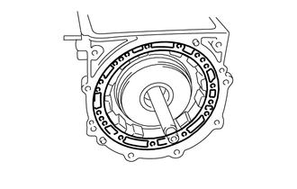
Install the new front oil pump cover gasket to the automatic transmission case.
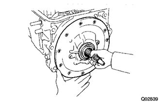
Install the oil pump assembly to the automatic transmission case.
Clean the bolt and bolt hole.
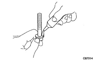
Apply adhesive to 2 or 3 threads of the 11 bolt.
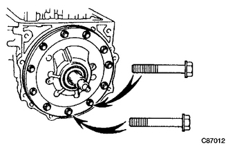
Install the oil pump assembly with the 11 bolts.
- Torque:
64 N*m (653 kgf*cm, 47 ft.*lbf)
50.INSTALL NO.2 ACCUMULATOR PISTON
Coat 2 new O-rings with ATF, and install them to the No.2 accumulator piston.
- NOTICE:
-
Be careful not to damage the O-rings.
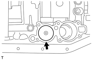
Coat a No.2 accumulator piston, a spring with ATF,and install them to the transmission case.
34421
51.INSTALL OVERDRIVE BRAKE ACCUMULATOR PISTON
Coat 2 new O-rings with ATF, and install them to the overdrive brake accumulator piston.
- NOTICE:
-
Be careful not to damage the O-rings.
Coat a overdrive brake accumulator piston, a spring with ATF,and install them to the transmission case.
35425A
52.INSTALL C-2 ACCUMULATOR PISTON
Coat 2 new O-rings with ATF, and install them to the C-2 accumulator piston.
- NOTICE:
-
Be careful not to damage the O-rings.
Coat a C-2 accumulator piston, a spring with ATF, and install them to the transmission case.
35893
53.INSTALL CENTER SUPPORT APPLY GASKET
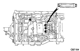
Coat 4 center support apply gaskets with ATF, and install them to the transmission case.
35410
54.INSTALL TRANSMISSION VALVE BODY ASSEMBLY
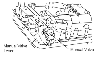
Align the transmission valve body with the manual valve lever.
Align of the manual valve with the transmission case.
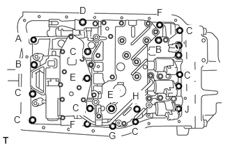
Install the transmission valve body assembly with the 21 bolts.
- Torque:
10 N*m (102 kgf*cm, 7 ft.*lbf)
- HINT:
Bolt length Bolt Length A 41 mm (1.6142 in.) B 32 mm (1.2598 in.) C 32 mm (1.2598 in.) D 45 mm (1.7717 in.) E 52 mm (2.0472 in.) F 28 mm (1.1024 in.) G 37.5 mm (1.4764 in.) H 57 mm (2.2441 in.) I 22 mm (0.8661 in.) J 22 mm (0.8661 in.)
82125J
55.INSTALL TRANSMISSION WIRE
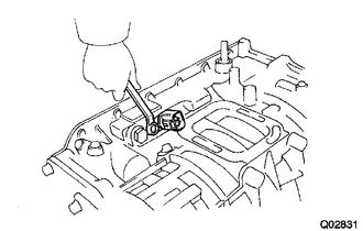
Install the transmission wire with a bolt.
- Torque:
8.0 N*m (82 kgf*cm, 71 in.*lbf)
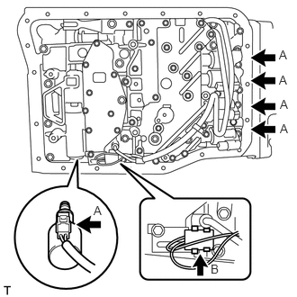
Connect the 5connectors to the solenoid valves.(A)
Connect the ATF temperature sensor's clamp.(B)
35261A
56.INSTALL THROTTLE PRESSURE ACCUMULATOR CYLINDER
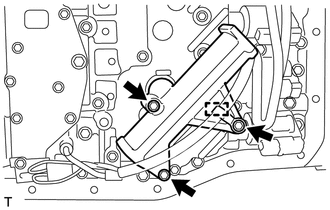
Coat a new center support apply gasket with ATF and install it to the throttle pressure accumulator cylinder.
Install the throttle pressure accumulator cylinder and clamp with the 3 bolts.
- Torque:
5.5 N*m (56 kgf*cm, 49 in.*lbf)
35330
57.INSTALL VALVE BODY OIL STRAINER ASSEMBLY
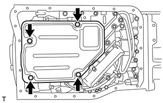
Install the new gasket on the valve body oil strainer assembly.
Install the valve body oil strainer assembly with the 4 bolts.
- Torque:
10 N*m (102 kgf*cm, 7 ft.*lbf)
35394
58.INSTALL TRANSMISSION OIL CLEANER MAGNET
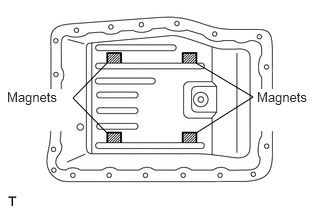
Clean the 4 transmission oil cleaner magnets and install them to the locations indicated in the illustration.
35106
59.INSTALL AUTOMATIC TRANSMISSION OIL PAN SUB-ASSEMBLY
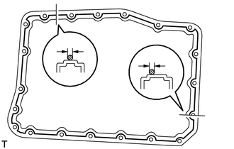
Apply seal packing in a continuous line as shown in the illustration.
- Seal packing:
Toyota Genuine Seal Packing 1281, Three Bond 1281 or equivalent
- Standard seal diameter:
2 to 3 mm (0.079 to 0.118 in.)
- NOTICE:
- ·
Remove any oil from the contact surface.
·Install the oil pan within 3 minutes after applying seal packing.
·Do not add ATF for at least 2 hours after the installation.
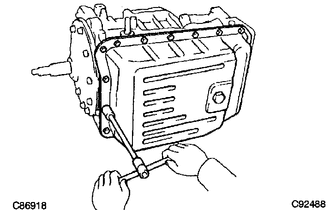
Install the automatic transmission oil pan sub-assembly with the 20bolts.
- Torque:
7.0 N*m (71 kgf*cm, 62 in.*lbf)
83181G
60.INSTALL SPEEDOMETER SENSOR
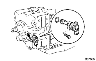
Coat a new O-ring with ATF, and install them to the speedometer sensor.
Install the speedometer sensor with a bolt.
- Torque:
- 13 N*m (133 kgf*cm, 10 ft.*lbf)
89413B
61.INSTALL TRANSMISSION REVOLUTION SENSOR
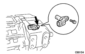
Install the transmission revolution sensor with a bolt.
- Torque:
8.0 N*m (82 kgf*cm, 71 in.*lbf)
35111
62.INSTALL AUTOMATIC TRANSMISSION HOUSING
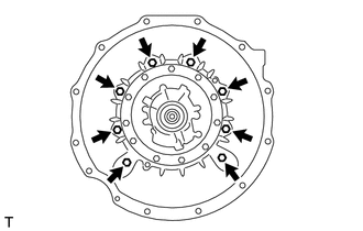
Coat a new automatic transmission case O-ring with ATF, and install them to the automatic transmission case.
Install the automatic transmission housing with the 8 bolts.
- Torque:
64 N*m (653 kgf*cm, 47 ft.*lbf)
32921C
63.INSTALL OIL COOLER TUBE UNION
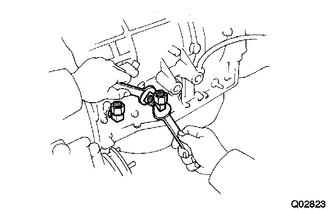
Coat a new O-ring with ATF, and install it to the oil cooler tube union(rear side).
Install the oil cooler tube union (rear side) to the automatic transmission case.
- Torque:
32 N*m (326 kgf*cm, 24 ft.*lbf)
Coat a new O-ring with ATF, and install it to the oil cooler tube union (front side).
Install the oil cooler tube union (front side) to the automatic transmission case.
- Torque:
32 N*m (326 kgf*cm, 24 ft.*lbf)
89429A
64.INSTALL TEMPERATURE SENSOR
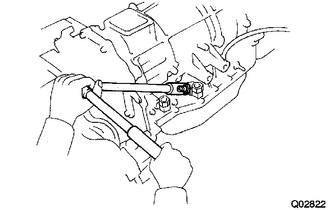
Install the temperature sensor to the oil cooler tube union (front side).
- Torque:
34 N*m (347 kgf*cm, 25 ft.*lbf)
84540
65.INSTALL PARK/NEUTRAL POSITION SWITCH ASSEMBLY
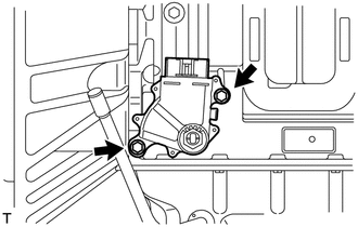
Install the park/neutral position switch to the automatic transmission.
Temporarily install the 2 bolts.
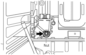
Install a new lock washer and the nut.
- Torque:
7.0 N*m (71 kgf*cm, 62 in.*lbf)
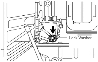
Using a screwdriver, bend the tabs of the lock washer.
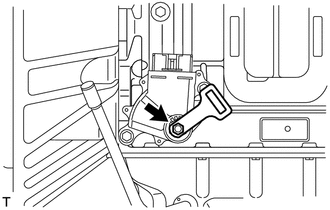
Temporarily install the transmission control shaft lever LH.
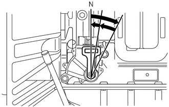
Turn the control shaft lever clockwise until it stops, and turn it counterclockwise 2 notches to set it to the N position.
Remove the transmission control shaft lever LH.
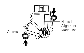
Align the neutral alignment mark line with the switch groove, and tighten the adjusting bolt.
- Torque:
13 N*m (133 kgf*cm, 10 ft.*lbf)
35573
66.INSTALL TRANSMISSION CONTROL SHAFT LEVER LH
Install the transmission control shaft lever LH with the 2 nuts.
- Torque:
13 N*m (133 kgf*cm, 10 ft.*lbf)
35104B
67.INSTALL NO.1 BREATHER PLUG (ATM)
Coat a new O-ring with ATF, and install it to the No.1 breather plug(ATM).
Install the breather tube to the No.1 breather plug(ATM).
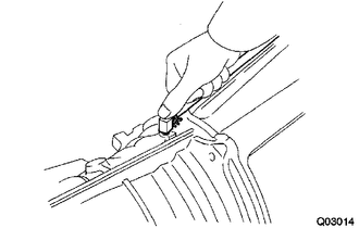
Install the No.1 breather plug(ATM) & breather tube to the transmission case.