CLUTCH CLUTCH PEDAL(w/o Turn Over) INSTALLATION
PROCEDURE

 31321
1.INSTALL CLUTCH PEDAL PAD
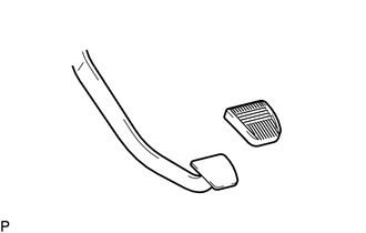
Install the clutch pedal pad to the clutch pedal sub-assembly.
31453B
2.INSTALL CLUTCH MASTER CYLINDER PUSH ROD CLEVIS BUSH
Install a new clutch master cylinder push rod clevis bush to the clutch pedal sub-assembly.
- HINT:
-
Install the clutch master cylinder push rod clevis bush from the left side of the vehicle.
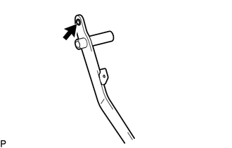
Apply MP grease to the inside of the clutch master cylinder push rod clevis bush.

|
MP grease |
31301B
3.INSTALL NO. 1 CLUTCH PEDAL CUSHION
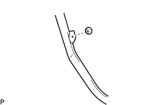
Install the No. 1 clutch pedal cushion to the clutch pedal sub-assembly.
31301C
4.INSTALL CLUTCH PEDAL BUSH
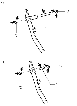
Apply MP grease to both sides of 2 new clutch pedal bushes and the clutch pedal shaft collar.
| *A | w/ Clutch Booster |
| *B | w/o Clutch Booster |
| *1 | Clutch Pedal Shaft Collar |
| *2 | Clutch Pedal Bush |
|
|
MP grease |
Install the 2 clutch pedal bushes and clutch pedal shaft collar to the clutch pedal sub-assembly.
31301A
5.INSTALL CLUTCH PEDAL SPRING
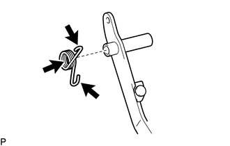
Apply MP grease to the inside of the clutch pedal spring and hook of the clutch pedal spring.
|
|
MP grease |
Install the clutch pedal spring to the clutch pedal sub-assembly.
31301
6.INSTALL CLUTCH PEDAL SUB-ASSEMBLY
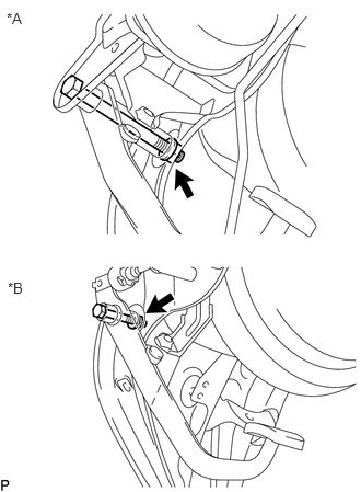
Install the clutch pedal sub-assembly to the clutch pedal bracket sub-assembly with the bolt, spring washer and nut.
- Torque:
30 N*m (306 kgf*cm, 22 ft.*lbf)
| *A | w/ Clutch Booster |
| *B | w/o Clutch Booster |
- NOTICE:
-
Turn the nut while holding the bolt.
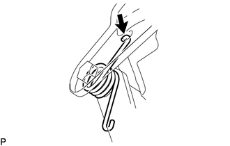
Connect the hook of the clutch pedal spring to the pedal bracket sub-assembly.
31453A
7.INSTALL CLUTCH MASTER CYLINDER PUSH ROD CLEVIS WITH HOLE PIN
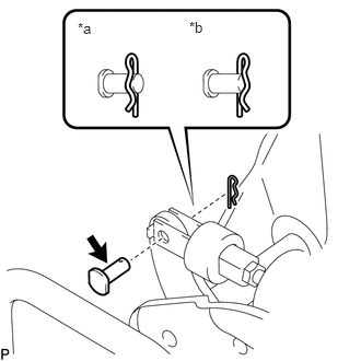
Apply MP grease to the clutch master cylinder push rod clevis with hole pin.
| *a | OK |
| *b | NG |
|
|
MP grease |
Install the clutch master cylinder push rod clevis with hole pin with a new clip as shown in the illustration.
8.INSTALL CLUTCH PEDAL STOPPER BOLT
w/o Exhaust Brake:
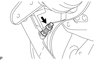
Install the pedal stopper bolt and lock nut to the clutch pedal bracket sub-assembly and temporarily install the lock nut.
- HINT:
-
Tighten the lock nut to the specified torque when adjusting the clutch pedal.
84640C
9.INSTALL EXHAUST RETARDER SWITCH ASSEMBLY
w/ Exhaust Brake:
Temporarily install the exhaust retarder switch assembly to the pedal bracket sub-assembly with the lock nut.
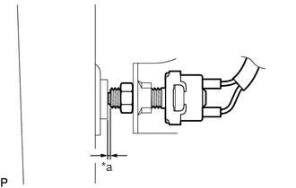
Adjust the exhaust retarder switch assembly by turning it so that the gap between the thread of the exhaust retarder switch assembly and No. 1 clutch pedal cushion reaches the standard clearance when the clutch pedal is released slowly.
- Standard Clearance:
0 to 0.5 mm (0 to 0.0196 in.)
| *a | 0 to 0.5 mm (0 to 0.0196 in.) |
- HINT:
-
Tighten the lock nut to the specified torque when adjusting the clutch pedal.
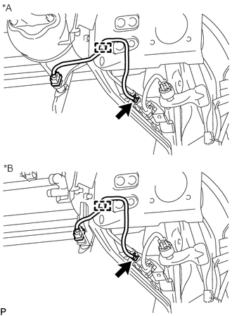
Connect the connector and attach the clamp.
| *A | w/ Clutch Booster |
| *B | w/o Clutch Booster |
10.INSPECT AND ADJUST CLUTCH PEDAL