1HZ ENGINE MECHANICAL CYLINDER HEAD REMOVAL
CAUTION / NOTICE / HINT
PROCEDURE

 1.DRAIN ENGINE COOLANT
17113
2.REMOVE INTAKE PIPE
3.REMOVE INJECTION PIPES
11452
4.REMOVE OIL DIPSTICK AND OIL DIPSTICK GUIDE
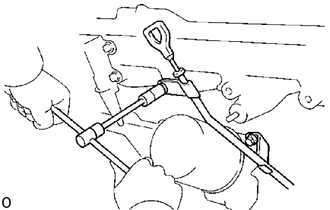
Remove the two bolts, and the oil dipstick guide assembly.
Remove the O-ring from the oil dipstick guide.
17111
5.REMOVE INTAKE MANIFOLD
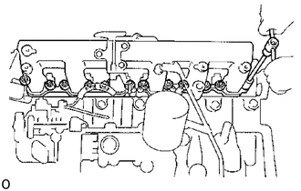
Disconnect the fuel hose from the nozzle leakage pipe.
(1PZ)
Remove the ten bolts, seal washers, intake manifold and five gaskets.
(1HZ and 1HD-T)
Remove the twelve bolts, seal washers, intake manifold and six gaskets.
16331
6.REMOVE WATER OUTLET
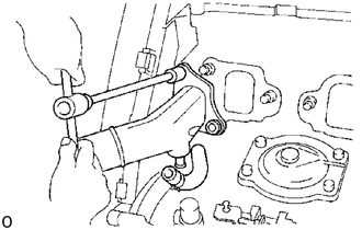
(1HD-T)
Disconnect the water by-pass hose.
Remove the two nuts, water outlet and gasket.
23760
7.REMOVE NOZZLE LEAKAGE PIPE
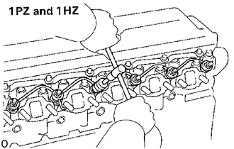
(1PZ and 1HZ)
(1PZ)
Remove the five union nuts, nozzle leakage pipe and five gaskets.
(1HZ)
Remove the six union nuts, nozzle leakage pipe and six gaskets.
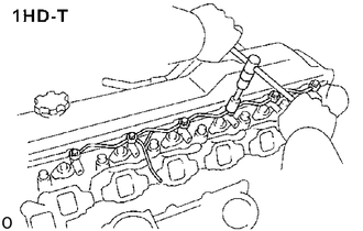
(1HD-T)
Remove the six hollow bolts, nozzle leakage pipe and twelve gaskets.
23600
8.REMOVE INJECTION NOZZLES
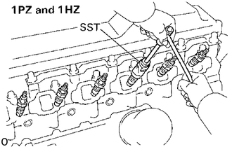
(1PZ and 1HZ)
(1PZ)
Using SST, remove the five injection nozzles, seats and gaskets.
- SST
- 09268-64010
(1HZ)
Using SST, remove the six injection nozzles, seats and gaskets.
- SST
- 09268-64010
- HINT:
-
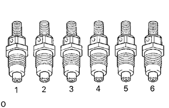
-
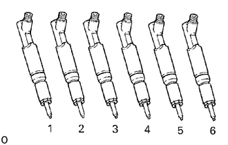
Arrange the injection nozzles in correct order.
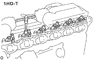
(1HD-T)
Remove the bolt, washer, nozzle holder, injection nozzle and seat.
Remove the O-ring from the injection nozzle.
- HINT:
-
-
Arrange the injection nozzles in correct order.
19850
9.REMOVE GLOW PLUGS
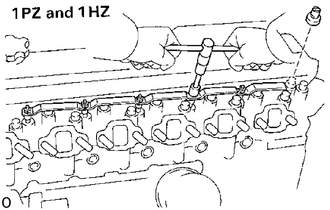
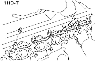
Remove the five screw grommets (1PZ) or six screw grommets (1HZ and 1HD-T).
Remove the five nuts (1PZ) or six nuts (1HZ and 1HD-T) and glow plug connector.
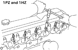
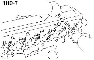
Using a 12 mm deep socket wrench, remove the five glow plugs (1PZ) or six glow plugs (1HZ and 1HD-T).
17141
10.REMOVE EXHAUST MANIFOLD (1PZ and 1HZ)
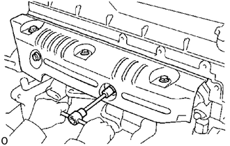
Remove the four bolts (1PZ) or five bolts (1HZ) and heat insulator.
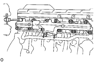
Remove the ten nuts (1PZ) or twelve nuts (1HZ), exhaust manifold and two gaskets.
11.REMOVE TURBOCHARGER AND EXHAUST MANIFOLD ASSEMBLY (1HD-T)
17141
12.SEPARATE EXHAUST MANIFOLDS
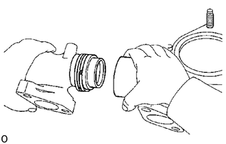
Separate the front and rear exhaust manifolds.
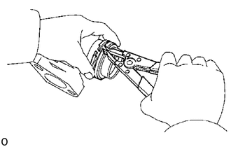
Using snap ring pliers, remove the two manifold rings.
13.REMOVE TIMING BELT AND PULLEYS
11385
14.REMOVE CAMSHAFT OIL SEAL RETAINER
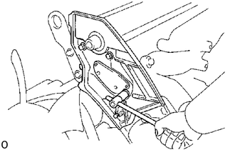
Remove the four bolts holding the camshaft oil seal retainer to the cylinder head.
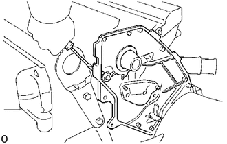
Pry out the camshaft oil seal retainer.
13511
15.REMOVE CAMSHAFT
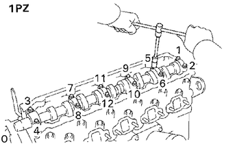
(1PZ)
Uniformly loosen and remove the twelve bearing cap bolts in several passes in the sequence shown.
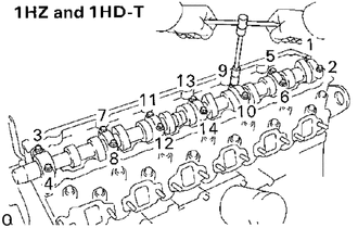
(1HZ and 1HD-T)
Uniformly loosen and remove the fourteen bearing cap bolts in several passes in the sequence shown.
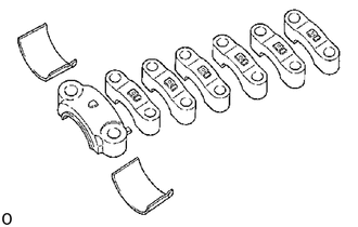
Remove the six bearing caps (1PZ) or seven bearing caps (1HZ and 1HD-T) and camshaft.
Remove the camshaft thrust plate.
- HINT:
-
-
Arrange the bearing caps and bearings in correct order.
11101
16.REMOVE CYLINDER HEAD
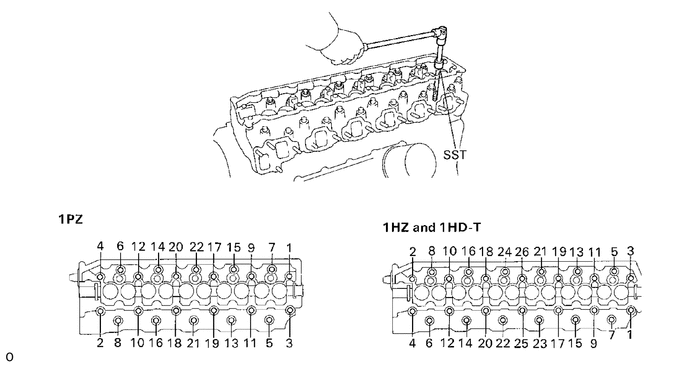
Using SST, uniformly loosen and remove the twenty-two cylinder head bolts (1PZ) or twenty-six cylinder head bolts (1HZ and 1HD-T) in several passes in the sequence shown.
- NOTICE:
-
Head warpage or cracking could result from removing bolts in incorrect order.
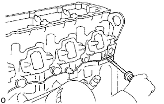
Lift the cylinder head from the dowels on the cylinder block and place the head on wooden blocks on a bench.
- HINT:
-
If the cylinder head is difficult to lift off, pry with a screwdriver between the cylinder head and block.
- NOTICE:
-
Be careful not to damage the cylinder head and cylinder block surfaces of cylinder head gasket side.