1HZ ENGINE MECHANICAL CYLINDER BLOCK CYLINDER BLOCK DISASSEMBLY
CAUTION / NOTICE / HINT
PROCEDURE

 11381
1.REMOVE REAR OIL SEAL RETAINER
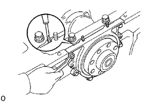
Remove the six bolts and retainer.
2.CHECK CONNECTING ROD THRUST CLEARANCE
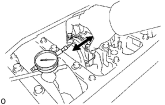
Using a dial indicator, measure the thrust clearance while moving the connecting rod back and forth.
- Standard thrust clearance:
0.10 - 0.20 mm (0.0038 - 0.0079 in.)
- Maximum thrust clearance:
0.30 mm (0.0118 in.)
If the thrust clearance is greater than maximum, replace the connecting rod assembly. If necessary, replace the crankshaft.
3.REMOVE CONNECTING ROD CAPS AND CHECK OIL CLEARANCE
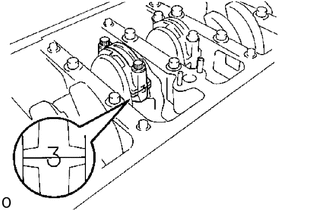
Using paint, place the matchmarks on the connecting rod and cap to ensure correct reassembly.
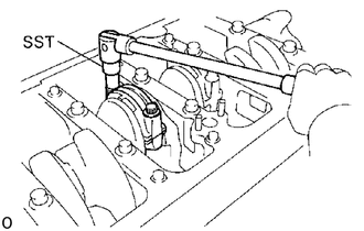
Using SST, remove the connecting rod cap bolts.
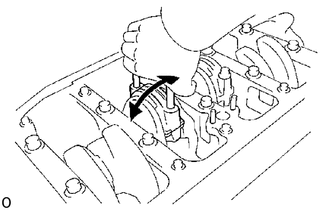
Using the removed connecting rod cap bolts, pry the connecting rod cap back and forth, and remove the connecting cap.
- HINT:
-
Keep the lower bearing inserted with the connecting rod cap.
Clean crank pin and bearing.
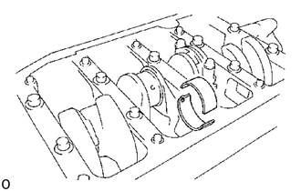
Check the crank pin and bearing for pitting and scratches.
If the crank pin or bearing is damaged, replace the bearings.
If necessary, grind or replace the crankshaft.
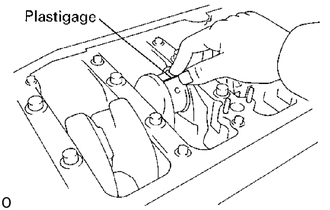
Lay a strip of Plastigage across the crank pin.
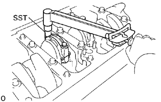
Install the connecting rod cap.
Click hereEngine / Hybrid System>1HZ (ENGINE MECHANICAL)>CYLINDER BLOCK>CYLINDER BLOCK ASSEMBLY
- Torque:
- 1st:
375 kg*cm (27 ft*lb, 39 N*m)
- 2nd:
turn 90°
- HINT:
-
Do not turn the crankshaft.
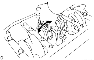
Remove the connecting rod cap.
(See procedure (b) and (c) above)
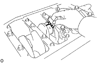
Measure the Plastigage at widest point.
- Standard oil clearance:
- STD:
0.036 - 0.054 mm (0.0014 - 0.0021 in.)
- U/S 0.25 and U/S 0.50:
0.037 - 0.077 mm (0.0015 - 0.0030 in.)
- Maximum oil clearance:
0.10 mm (0.0039 in.)
If the oil clearance is greater than maximum, replace the bearings. If necessary, grind or replace the crankshaft.
- HINT:
-
If using a standard bearing, replace with one having the same number. If the number of the bearing cannot be determined, select the correct bearing by adding together the numbers inprinted on the crankshaft and connecting rod, then selecting the bearing with the same number as the total. There are five sizes of standard bearings, marked "2", "3", "4", "5" and "6" accordingly.
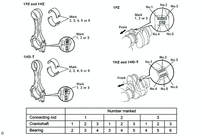
-
EXAMPLE: Connecting rod "2" + Crankshaft "1" = Total number (Use bearing "3")
(Reference)
- Connecting rod big end inner diameter:
- Mark "1":
62.014 - 62.020 mm (2.4415 - 2.4417 in.)
- Mark "2":
62.020 - 62.026 mm (2.4417 - 2.4420 in.)
- Mark "3":
62.026 - 62.032 mm (2.4420 - 2.4422 in.)
- Crankshaft pin diameter:
- Mark "1":
58.994 - 59.000 mm (2.3226 - 2.3228 in.)
- Mark "2":
58.988 - 58.994 mm (2.3224 - 2.3226 in.)
- Mark "3":
58.982 - 58.988 mm (2.3221 - 2.3224 in.)
- Standard sized bearing center wall thickness:
- Mark "2":
1.486 - 1.489 mm (0.0585 - 0.0586 in.)
- Mark "3":
1.489 - 1.492 mm (0.0586 - 0.0587 in.)
- Mark "4":
1.492 - 1.495 mm (0.0587 - 0.0589 in.)
- Mark "5":
1.495 - 1.498 mm (0.0589 - 0.0590 in.)
- Mark "6":
1.498 - 1.501 mm (0.0590 - 0.0591 in.)
Completely remove the Plastigage.
4.REMOVE PISTON AND CONNECTING ROD ASSEMBLIES
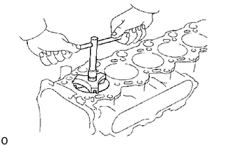
Remove the all carbon from the top of the cylinder.
Push the piston, connecting rod assembly and upper bearing through the top of the cylinder block.
- HINT:
-
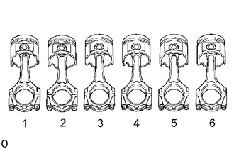
- ·
Keep the bearings, connecting rod and cap together.
·Arrange the piston and connecting rod assemblies in correct order.
5.CHECK CRANKSHAFT THRUST CLEARANCE
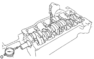
Using a dial indicator, measure the thrust clearance while prying the crankshaft back and forth with a screwdriver.
- Standard thrust clearance:
0.04 - 0.24 mm (0.0016 - 0.0094 in.)
- Maximum thrust clearance:
0.30 mm (0.0118 in.)
If the thrust clearance is greater than maximum, replace the thrust washers as a set.
- Thrust washer thickness:
2.930 - 2.980 mm (0.1154 - 0.1173 in.)
6.REMOVE MAIN BEARING CAP AND CHECK OIL CLEARANCE
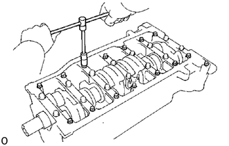
Remove the thirteen bolts (1PZ) or fifteen bolts (1HZ and1HD-T).
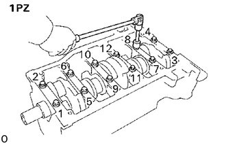
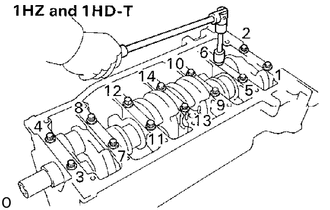
Uniformly loosen and remove the main bearing cap bolts in several passes in the sequence shown.
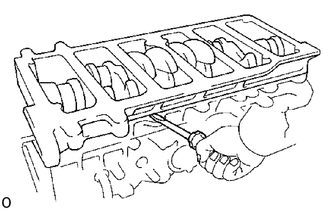
Using a screwdriver, pry out the main bearing cap.
- HINT:
-
Keep the lower main bearings and main bearing cap together.
- NOTICE:
-
Do not scratch the surface which will be coated with FIPG.
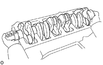
Lift out the crankshaft.
- HINT:
-
Keep the upper main bearings and thrust washers together with the cylinder block.
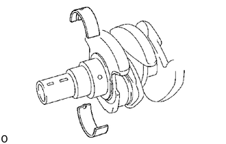
Clean each main journal and bearing.
Check each main journal and bearing for pitting and scratches.
If the journal or bearing are damaged, replace the bearings.
If necessary, grind or replace the crankshaft.
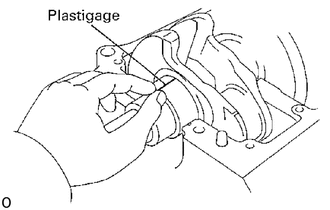
Place the crankshaft on the cylinder block.
Lay a strip of Plastigage across each journal.
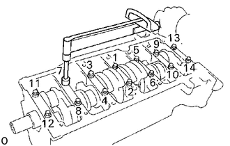
Install the main bearing cap with the bearings.
Click hereEngine / Hybrid System>1HZ (ENGINE MECHANICAL)>CYLINDER BLOCK>CYLINDER BLOCK ASSEMBLY
- Torque:
- 1st:
1,050 kg*cm (76 ft*lb, 103 N*m)
- 2nd:
turn 90°
- HINT:
-
Do not turn the crankshaft.
Remove the main bearing cap bolts and cap.
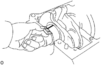
Measure the Plastigage at its widest point.
- Standard clearance:
- STD:
0.036 - 0.054 mm (0.0014 - 0.0021 in.)
- U/S 0.25 and U/S 0.50:
0.037 - 0.077 mm (0.0015 - 0.0030 in.)
- Maximum clearance:
0.10 mm (0.0039 in.)
If the oil clearance is greater than maximum, replace the bearings. If necessary. grind or replace the crankshaft.
- HINT:
-
If replacing a main bearing, replace it with one that has the same number. If the number of the main bearing cannot be determined, select the correct main bearing by adding together the numbers imprinted on the cylinder block sub-assembly and crankshaft, and then refer to the table below for the appropriate main bearing number. There are 6 sizes of standard main bearings, marked "2", "3", "4", "5", "6" and "7" accordingly.
-
EXAMPLE: Main bearing cap "2" + Crankshaft "1" = Total number (Use bearing "3")
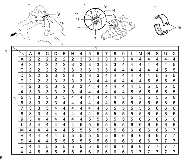 6.094,0.854 6.438,1.01 6.438,1.01 6.083,1.167 true 1.396,0.625 1.542,0.625 false 1.438,0.76 1.594,0.76 1.594,0.76 1.594,0.646 false 1.771,0.521 2.031,0.521 true 1.635,0.906 1.635,0.625 true 2.042,0.656 1.885,0.656 1.885,0.656 1.75,0.563 true 1.813,1.031 1.813,0.865 1.813,0.865 1.677,0.604 true 2.177,0.844 1.938,0.844 1.938,0.844 1.708,0.583 true 2.958,0.708 3.375,0.708 true 3.5,0.625 3.615,0.26 3.615,0.26 3.76,0.26 true 2.917,0.51 3.094,0.51 3.094,0.51 3.448,0.667 true 3.583,0.604 3.854,0.396 3.854,0.396 4.042,0.396 true 3.01,1.021 3.167,1.021 3.167,1.021 3.448,0.833 true 3.49,1.292 3.49,1.146 3.49,1.146 3.531,0.813 true 3.594,0.75 3.917,0.573 3.917,0.573 4.094,0.573 true 1.229,0.521 1.406,0.719 0.177,0.198 10 true *a 1.271,0.688 1.438,0.865 0.167,0.177 10 true *b 1.542,0.906 1.729,1.083 0.188,0.177 10 true *c 1.708,1.052 1.896,1.219 0.188,0.167 10 true *d 2.198,0.76 2.396,0.938 0.198,0.177 10 true *e 2.083,0.583 2.229,0.771 0.146,0.188 10 true *f 2.063,0.406 2.25,0.615 0.188,0.208 10 true *g 1.552,0.354 1.792,0.521 0.24,0.167 10 false *h 6.49,0.938 6.708,1.146 0.219,0.208 10 false *h 3.281,0.375 3.458,0.531 0.177,0.156 10 true *h 2.781,0.615 2.979,0.823 0.198,0.208 10 false *a 2.74,0.427 2.938,0.604 0.198,0.177 10 false *b 3.792,0.167 3.979,0.344 0.188,0.177 10 true *c 4.073,0.313 4.26,0.479 0.188,0.167 10 true *d 2.823,0.938 3.021,1.115 0.198,0.177 10 false *e 3.417,1.313 3.563,1.5 0.146,0.188 10 true *f 4.125,0.479 4.313,0.688 0.188,0.208 10 true *g 1.031,0.115 1.344,0.313 0.313,0.198 10 false *i 3.073,0.094 3.385,0.292 0.313,0.198 10 false *j 5.604,0.167 5.917,0.365 0.313,0.198 10 false *k 0.49,3.531 0.802,3.729 0.313,0.198 10 false *i 3.469,1.677 3.781,1.875 0.313,0.198 10 false *j 0.177,1.792 0.375,2.031 0.198,0.24 10 false *l
*a No. 1 *b No. 2 *c No. 3 *d No. 4 *e No. 5 *f No. 6 *g No. 7 *h Mark *i Cylinder Block Journal Code *j Crankshaft Journal Code *k Main Bearing Code *l Main Bearing Chart 
front - -
- Cylinder Block Main Journal Bore Diameter:
Item Specified Condition Mark A 71.000 to 71.001 mm (2.79527 to 2.79531 in.) Mark B 71.001 to 71.002 mm (2.79531 to 2.79535 in.) Mark C 71.002 to 71.003 mm (2.79535 to 2.79539 in.) Mark D 71.003 to 71.004 mm (2.79539 to 2.79543 in.) Mark E 71.004 to 71.005 mm (2.79543 to 2.79547 in.) Mark H 71.005 to 71.006 mm (2.79547 to 2.79551 in.) Mark 4 71.006 to 71.007 mm (2.79551 to 2.79555 in.) Mark 5 71.007 to 71.008 mm (2.79555 to 2.79558 in.) Mark 6 71.008 to 71.009 mm (2.79558 to 2.79562 in.) Mark 7 71.009 to 71.010 mm (2.79562 to 2.79566 in.) Mark 8 71.010 to 71.011 mm (2.79566 to 2.79570 in.) Mark 9 71.011 to 71.012 mm (2.79570 to 2.79574 in.) Mark L 71.012 to 71.013 mm (2.79574 to 2.79578 in.) Mark M 71.013 to 71.014 mm (2.79578 to 2.79582 in.) Mark R 71.014 to 71.015 mm (2.79582 to 2.79586 in.) Mark S 71.015 to 71.016 mm (2.79586 to 2.79590 in.) Mark U 71.016 to 71.017 mm (2.79590 to 2.79594 in.) Mark X 71.017 to 71.018 mm (2.79594 to 2.79598 in.)
- Crankshaft Main Journal Diameter:
Item Specified Condition Mark A 66.999 to 67.000 mm (2.63775 to 2.63779 in.) Mark B 66.998 to 66.999 mm (2.63771 to 2.63775 in.) Mark C 66.997 to 66.998 mm (2.63767 to 2.63771 in.) Mark D 66.996 to 66.997 mm (2.63763 to 2.63767 in.) Mark E 66.995 to 66.996 mm (2.63759 to 2.63763 in.) Mark H 66.994 to 66.995 mm (2.63755 to 2.63759 in.) Mark 4 66.993 to 66.994 mm (2.63751 to 2.63755 in.) Mark 5 66.992 to 66.993 mm (2.63748 to 2.63751 in.) Mark 6 66.991 to 66.992 mm (2.63744 to 2.63748 in.) Mark 7 66.990 to 66.991 mm (2.63740 to 2.63744 in.) Mark 8 66.989 to 66.990 mm (2.63736 to 2.63740 in.) Mark 9 66.988 to 66.989 mm (2.63732 to 2.63736 in.) Mark L 66.987 to 66.988 mm (2.63728 to 2.63732 in.) Mark M 66.986 to 66.987 mm (2.63724 to 2.63728 in.) Mark R 66.985 to 66.986 mm (2.63720 to 2.63724 in.) Mark S 66.984 to 66.985 mm (2.63716 to 2.63720 in.) Mark U 66.983 to 66.984 mm (2.63712 to 2.63716 in.) Mark X 66.982 to 66.983 mm (2.63708 to 2.63712 in.)
- Standard Main Bearing Center Wall Thickness:
Item Specified Condition Mark 2 1.982 to 1.985 mm (0.0780 to 0.0781 in.) Mark 3 1.985 to 1.988 mm (0.0781 to 0.0783 in.) Mark 4 1.988 to 1.991 mm (0.0783 to 0.0784 in.) Mark 5 1.991 to 1.994 mm (0.0784 to 0.0785 in.) Mark 6 1.994 to 1.997 mm (0.0785 to 0.0786 in.) Mark 7 1.997 to 2.000 mm (0.0786 to 0.0787 in.)
Completely remove the Plastigage.
13411
7.REMOVE CRANKSHAFT
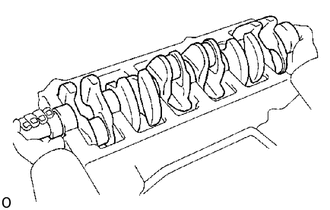
Lift out the crankshaft.
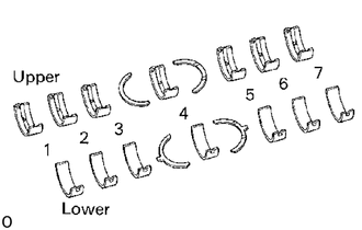
Remove the upper main bearings and thrust washers from the cylinder block.
- HINT:
-
Arrange the main bearings and thrust washers in correct order.
8.REMOVE CHECK VALVES AND OIL NOZZLES
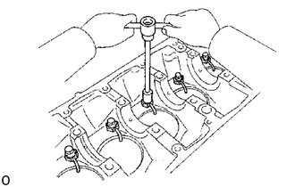
Remove the five (1PZ) or six (1HZ and 1HD-T) check valves and oil nozzles.
9.REMOVE CYLINDER BLOCK OIL HOLE GASKET
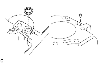
10.REMOVE CYLINDER BLOCK ORIFICE