1HZ ENGINE MECHANICAL CYLINDER BLOCK CYLINDER BLOCK ASSEMBLY
CAUTION / NOTICE / HINT
Click hereEngine / Hybrid System>1HZ (ENGINE MECHANICAL)>CYLINDER BLOCK>COMPONENTS
- HINT:
- ·
Thoroughly clean all parts to be assembled.
·Before installing the parts, apply new engine oil to all sliding and rotating surfaces.
·Replace all gaskets, 0-rings and oil seals with new parts.
PROCEDURE

 1.INSTALL NEW CYLINDER BLOCK OIL HOLE GASKET
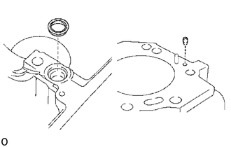
2.INSTALL CYLINDER BLOCK ORIFICE
3.INSTALL OIL NOZZLES AND CHECK VALVES
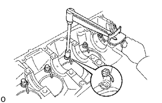
Align the pin of the oil nozzle with the pin hole of the cylinder block.
Install the oil nozzle with the check valve. Install the five (1PZ) or six (1HZ and 1HD-T) oil nozzles and check valves.
- Torque:
275 kg*cm (20 ft*lb, 27 N*m)
4.INSTALL MAIN BEARINGS
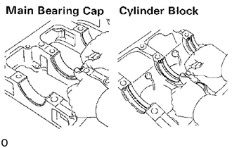
Align the bearing claw with the claw groove of the main bearing cap or cylinder block.
Install the bearings in the cylinder block and main bearing cap.
- NOTICE:
-
Install the bearing with the oil hole in the cylinder block.
13411
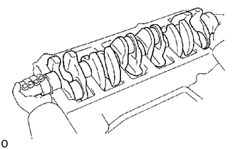
5.PLACE CRANKSHAFT ON CYLINDER BLOCK
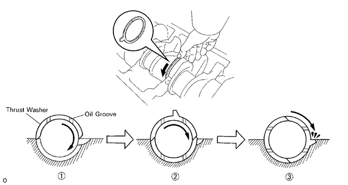
6.INSTALL THRUST WASHERS
Push the crankshaft toward the front (rear) side.
Install the thrust washers to the No.4 main journal position of the cylinder block with the oil grooves facing outward.
7.INSTALL MAIN BEARING CAP
Install main bearing cap on cylinder block
Remove any old packing (FIPG) material and be careful not to drop any oil the contact surfaces of the main bearing cap and cylinder block.
Thoroughly clean all components to remove all the loose material.
Using a non-residue solvent, clean both sealing surfaces.
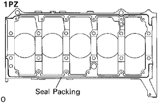
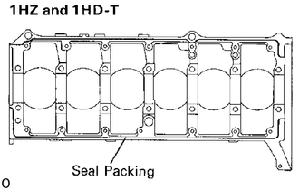
Apply seal packing to the cylinder block as shown in the illustration.
- Seal packing:
Part No. 08826-00080 or equivalent
Install a nozzle that has been cut to a 5 mm (0.20 in.) opening.
Parts must be assembled within 5 minutes of application.
Otherwise the material must be removed and reapplied.
Immediately remove nozzle from the tube and reinstall cap.
Install main bearing cap bolts
- HINT:
- ·
The main bearing cap bolts are tightened in two progressive steps.
·If any of the main bearing bolts break or deform, replace them.
Apply a light coat of engine oil on the threads and under the heads of the main bearing cap bolts.
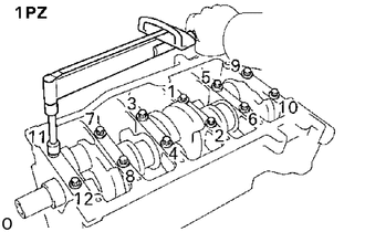
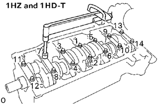
1st, install and uniformly tighten the twelve (1PZ) or fourteen (1HZ and 1HD-T) main bearing cap bolts in several passes in the sequence shown.
- Torque:
1,050 kg*cm (76 ft*lb, 103 N*m)
If any one of the main bearing cap bolts does not meet the torque specification, replace the main bearing cap bolt.
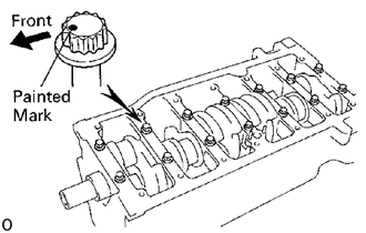
Mark the front of the main bearing cap bolt head with paint.
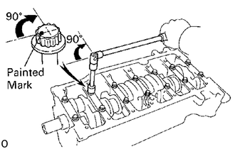
2nd, retighten the main bearing cap bolts 90° in the numerical order shown above.
Check that the painted mark is now at a 90° angle to the front.
Check that the crankshaft turns smoothly.
Check the crankshaft thrust clearance.
Click hereEngine / Hybrid System>1HZ (ENGINE MECHANICAL)>CYLINDER BLOCK>CYLINDER BLOCK DISASSEMBLY
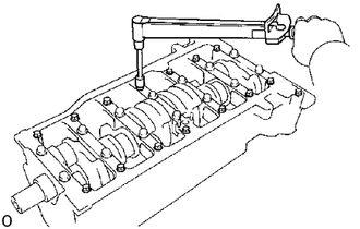
Install and torque the thirteen bolts (1PZ) or fifteen bolts (1HZ and 1HD-T).
- Torque:
185 kg*cm (13 ft*lb, 18 N*m)
8.INSTALL PISTON AND CONNECTING ROD ASSEMBLIES
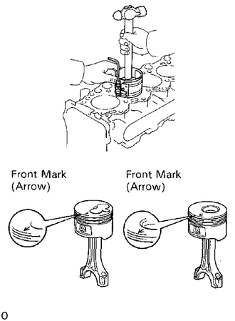
Using a piston ring compressor, push the correctly numbered piston and connecting rod assemblies into each cylinder with the front mark of the piston facing forward.
9.INSTALL CONNECTING ROD CAPS
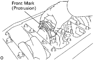
Place connecting rod cap on connecting rod
Match the numbered connecting rod cap with the connecting rod.
Install the connecting rod cap with the front mark facing forward.
Install connecting rod cap bolts
- HINT:
- ·
The connecting rod cap bolts are tightened in two progressive steps.
·If any of the connecting rod bolts break or deform, replace them.
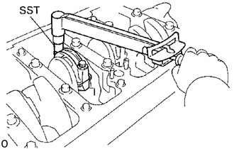
Apply a light coat of engine oil on the threads and under the heads of the connecting rod cap bolts.
1st, using SST, install and alternately tighten the bolts of the connecting rod cap in several passes.
- Torque:
375 kg*cm (27 ft*lb, 39 N*m)
If any one of the connecting rod cap bolts does not meet the torque specification, replace the cap bolt.
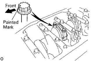
Mark the front of the connecting rod cap bolt with paint.
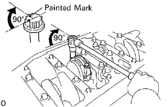
2nd, retighten the connecting rod cap bolts by an additional 90°.
Check that the painted mark is now at a 90° angle to the front.
Check that the crankshaft turns smoothly.
Check the connecting rod thrust clearance.
Click hereEngine / Hybrid System>1HZ (ENGINE MECHANICAL)>CYLINDER BLOCK>CYLINDER BLOCK DISASSEMBLY
11381
10.INSTALL REAR OIL SEAL RETAINER
Remove any old packing (FIPG) material and be careful not to drop any oil on the contact surfaces of the rear oil seal retainer and cylinder block.
Using a razor blade and gasket scraper, remove all the old packing (FIPG) material from the gasket surfaces and sealing groove.
Thoroughly clean all components to remove all the loose material.
Using a non-residue solvent, clean both sealing surfaces.
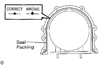
Apply seal packing to the rear oil seal retainer as shown in the illustration.
- Seal packing:
Part No.08826-00080 or equivalent
Install a nozzle that has been cut to a 2 - 3 mm (0.08 - 0.12 in.) opening.
Parts must be assembled within 5 minutes of application. Otherwise the material must be removed and reapplied.
Immediately remove nozzle from the tube and reinstall cap.
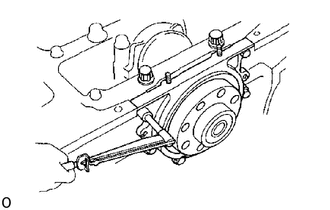
Install the retainer with the six bolts.
- Torque:
65 kg*cm (56 in.*lb, 6.4 N*m)