1HZ ENGINE MECHANICAL ENGINE TUNE-UP INJECTION TIMING ADJUSTMENT
PROCEDURE

 1.REMOVE TIMING BELT COVER (1PZ)
2.SET NO.1 CYLINDER TO TDC/COMPRESSION (1PZ)
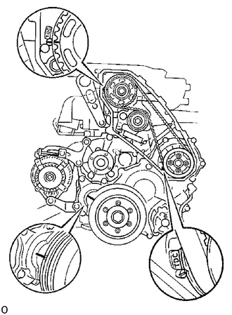
Turn the crankshaft pulley clockwise, and align each pulley groove with the timing marks (TDC mark) as shown in the illustration.
3.SET NO.1 OR NO.6 CYLINDER TO TDC/COMPRESSION (1HZ and 1HD-T)
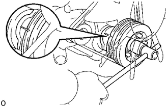
Turn the crankshaft pulley clockwise, and align each pulley groove with the timing marks (TDC mark) as shown in the illustration.
4.REMOVE AIR CONTROL VALVE (ACV) (1HD-T w/ BACS)
5.INSTALL SST AND DIAL INDICATOR
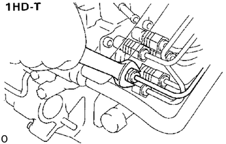
(1HD-T)
Loosen the union nut of the No.5 cylinder injection pipe.
Remove the plug bolt from the distributive head plug of the injection pump.
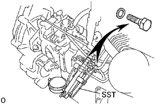
Install SST (plunger stroke measuring tool) and a dial indicator to the plug bolt hole of distributive head plug.
- SST
- 09275-54011
6. RELEASE ACSD ADVANCE (w/ ACSD)
Using a screwdriver, turn the cold starting lever counterclockwise approx. 20°.
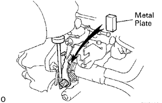
Put a metal plate (thickness of 3.5 - 7.5 mm (0.135 - 0.295 in.)) between the cold starting lever and thermo wax plunger.
7.ADJUST INJECTION TIMING
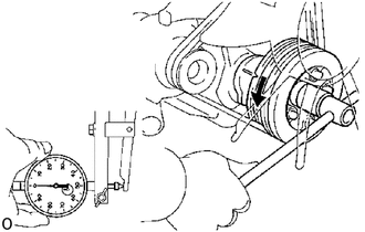
Slowly rotate the crankshaft pulley counterclockwise and set the dial indicator at 0 mm (0 in.) when the dial indicator reaches the minimum value.
- NOTICE:
-
Compared with previous four cylinder engines, the 0 mm (0 in.) position (crank angle) is reduced, so perform the operation carefully. (ex. 1 PZ)
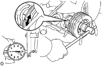
Turn the crankshaft to the left and right and check that the dial indicator shows the minimum value.
- NOTICE:
-
Make sure that the minimum value is set at 0 mm (0 in.).
Slowly rotate the crankshaft pulley clockwise until pulley groove is aligned with the timing gear cover groove.
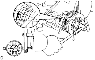
Measure the plunger stroke.
- Plunger stroke:
- 1PZ:
0.82-0.88 mm (0.0323-0.0346 in.)
- 1HZ:
1.03-1.09 mm (0.0406-0.0429 in.)
- 1HD-T:
1.29-1.35 mm (0.0508-0.0531 in.)
Repeat steps (a) to (c) several times.
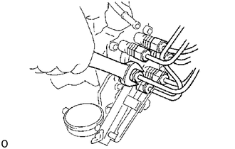
Loosen the following nuts and bolt:
(1PZ)
Five union nuts of injection pipes at injection pump side.
(1HZ)
Six union nuts of injection pipes at injection pump side.
(1HD-T)
Five union nuts of injection pipes at injection pump side.
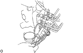
Bolt holding injection pump to injection pump stay.
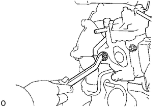
Two nuts holding injection pump to timing gear case.
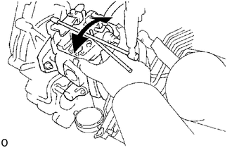
Adjust plunger stroke by slightly tilting the injection pump body.
If the stroke is less than specification, tilt the pump toward the engine.
If the stroke is greater than specification, tilt the pump away from the engine.
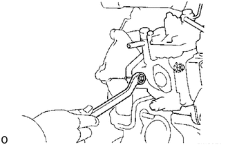
Tighten the following nuts and bolt:
Two nuts holding injection pump to timing gear case.
- Torque:
185 kg*cm (13 ft*lb, 18 N*m)
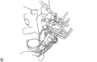
Bolt holding injection pump to injection pump stay.
- Torque:
700 kg*cm (61 ft*lb, 69 N*m)
Recheck the plunger stroke.
8.REMOVE METAL PLATE (w/ ACSD)
9.REMOVE SST AND DIAL INDICATOR
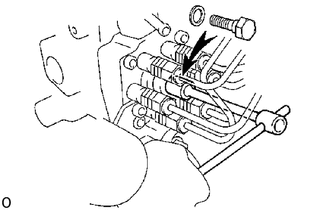
Remove SST and the dial indicator.
- SST
- 09275-54011
Install a new gasket and the plug bolt of the distributive head plug.
- Torque:
- 1PZ and 1HZ:
170 kg*cm (12 ft*lb, 17 N*m)
- 1HD-T:
260 kg*cm (19 ft*lb, 25 N*m)
10. TORQUE UNION NUTS OF INJECTION PIPES
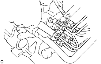
- Torque:
- 1PZ and 1HZ:
170 kg*cm (12 ft*lb, 17 N*m)
- 1HD-T:
250 kg*cm (18 ft*lb, 25 N*m)
11.INSTALL AIR CONTROL VALVE (ACV) (1HD-T w/BACS)
12.INSTALL TIMING BELT COVER
13. START ENGINE AND CHECK FOR LEAKS