1HZ ENGINE MECHANICAL VALVE CLEARANCE ADJUSTMENT
CAUTION / NOTICE / HINT
- HINT:
-
Adjust the valve clearance while the engine is cold.
PROCEDURE

 1.REMOVE INTAKE PIPE
2.REMOVE CYLINDER HEAD COVER
3. SET NO.1 CYLINDER TO TDC/COMPRESSION
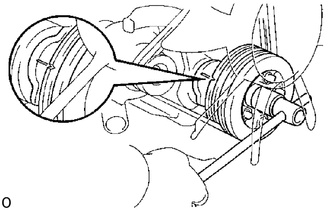
Turn the crankshaft pulley clockwise, and align its groove with the timing gear cover groove.
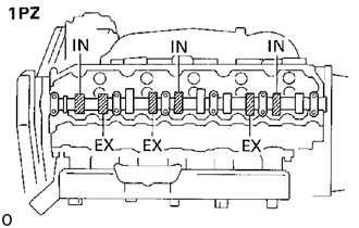
(1PZ)
Check that the valve lifters on the No.1 cylinder are loose and exhaust valve lifter on the No.5 cylinder is tight.
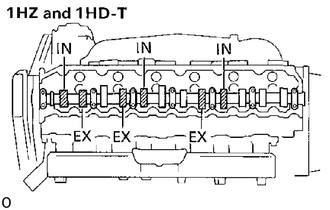
(1HZ and 1HD-T)
Check that the valve lifters on the No.1 cylinder are loose and valve lifters on the No.6 cylinder are tight.
If not, turn the crankshaft one revolution (360°) and align the mark as above.
4.ADJUST VALVE CLEARANCE
Check only those valves indicated in the illustration.
Using a thickness gauge, measure the clearance between the valve lifter and camshaft.
Record the valve clearance measurements which are out of specification. They will be used later to determine the required replacement adjusting shim.
- Valve clearance (Cold):
Intake 0.15 - 0.25 mm (0.006 - 0.010 in.)
Exhaust 0.35 - 0.45 mm (0.014 - 0.018 in.)
Turn the crankshaft one revolution (360°), and align the mark as above (See procedure step 3).
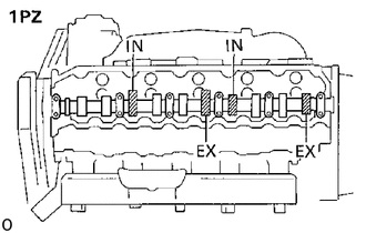
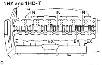
Check only the valves indicated in the illustration.
Measure the valve clearance.
(See procedure step (a))
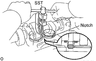
Remove the adjusting shim.
Turn the crankshaft to position the cam lobe of the camshaft on the adjusting valve upward.
Using SST, press down the valve lifter.
- SST
- 09248-64011
- HINT:
-
Before pressing down the valve lifter, position the notch on the exhaust manifold side.
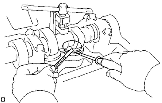
Remove the adjusting shim with a small screwdriver and magnetic finger.
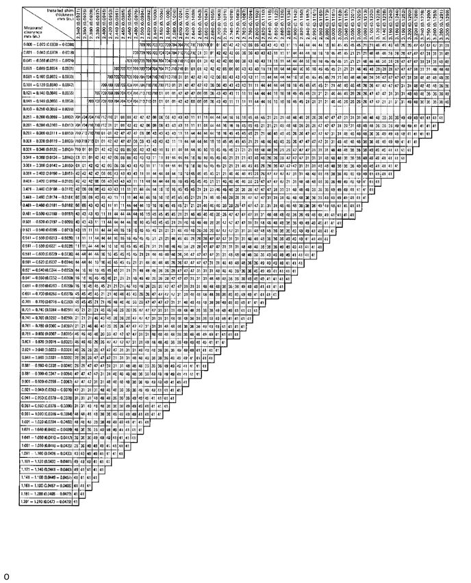
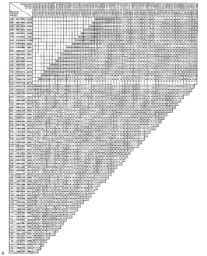
Determine the replacement adjusting shim size by using following (Formula or Charts):
Using a micrometer, measure the thickness of the removed shim.
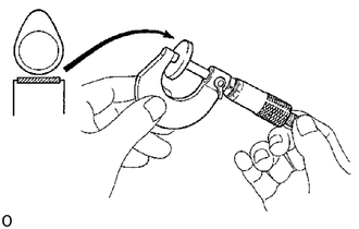
Calculate the thickness of the new shim so the valve clearance comes within specified value.
T .......... Thickness of used shim
A .......... Measured valve clearance
N .......... Thickness of new shim
Intake N = T + (A-0.20 mm (0.008 in.))
Exhaust N = T + (A-0.40 mm (0.016 in.))
Select a new shim with a thickness as close as possible to the calculated values.
- HINT:
-
Shims are available in twenty sizes in increments of 0.05 mm (0.0020 in.), from 2.35 mm (0.0925 in.) to 3.30 mm (0.1299 in.)
Install a new adjusting shim.
Place a new adjusting shim on the valve lifter.
Remove SST.
- SST
- 09248-64011
Recheck the valve clearance.
5.REINSTALL CYLINDER HEAD COVER
6.REINSTALL INTAKE PIPE