14B ENGINE MECHANICAL CYLINDER HEAD CYLINDER HEAD REMOVAL
PROCEDURE

 1.DRAIN ENGINE COOLANT
12261
2.REMOVE PCV HOSE
23600
3.REMOVE INJECTION NOZZLES
4.REMOVE GLOW PLUGS (3B)
Remove the 4 screw grommets.
Remove the 4 nuts and glow plug connector.
Remove the 4 glow plugs.
5.REMOVE OIL DIPSTICK AND GUIDE (BB)
25706
6.REMOVE VACUUM PIPE (BB)
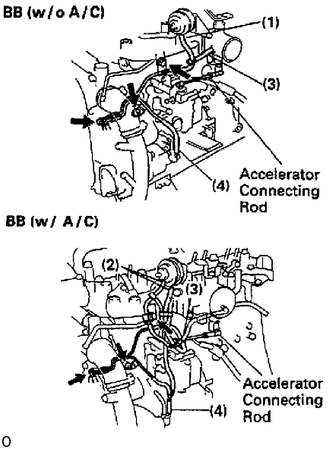
Disconnect these vacuum hoses:
w/o A/C
Vacuum hose from idle-up actuator
w/ A/C
2 vacuum hoses from idle-up actuator
Vacuum hose from venturi or intake shutter
Vacuum hose from vacuum pump
Remove the 3 bolts and vacuum pipe.
21905C
7.REMOVE ACCELERATOR CONNECTING ROD
17111
8.REMOVE INTAKE MANIFOLD
w/ ACSD for 14B
Remove the holding bolt and nut the water bypass pipe to the intake manifold and venturi.
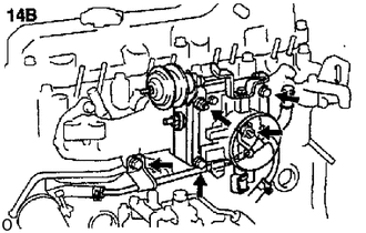
14B:
Remove the 2 bolts, 2 nuts (w/o ACSD), nut (w/ ACSD), idle-up actuator, the venturi and intake heater assembly.
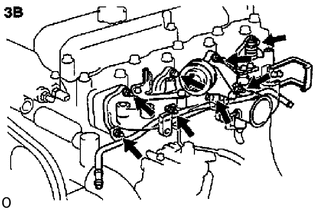
3B:
Remove the 3 bolts, oil dipstick guide support (BU), 5 nuts, PS return pipe, intake manifold, venturi assembly and gasket.
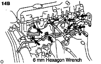
14B:
Using a 6 mm hexagon wrench, remove the bolt.
14B:
Remove the 2 bolts, oil dipstick guide support (BB), 5 nuts, PS return pipe, intake manifold and gasket.
9.REMOVE REAR ENGINE HANGER
16333
10.REMOVE WATER OUTLET ASSEMBLY
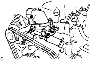
Remove the 2 nuts holding the water outlet housing to the cylinder head.
Disconnect the water bypass hose from the water pump, and remove the water outlet assembly.
16381
11.REMOVE DRIVE BELT ADJUSTING BAR
Remove the 2 bolts and adjusting bar.
17141
12.REMOVE EXHAUST MANIFOLD
Bolt tightening type:
Remove the 3 bolts and heat insulator.
Nut tightening type:
Remove the 3 nuts, 6 plate washers, heat insulator and 6 spacers.
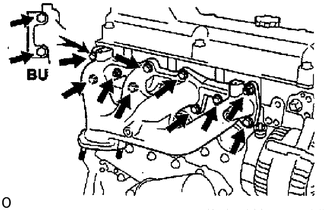
Remove the 8 bolts, 2 nuts, exhaust manifold, No.2 heat insulator (BU) and gasket.
11201
13.REMOVE CYLINDER HEAD COVER
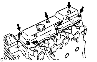
Remove the 4 bolts, 2 nuts, 6 cushions, cylinder head cover and gasket.
13901
14.REMOVE VALVE ROCKER SHAFT ASSEMBLY
Loosen the lock nuts and adjusting screws.
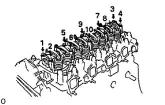
Uniformly loosen and remove the 10 bolts, in several passes, in the sequence shown.
Remove the rocker shaft assembly.
15.REMOVE PUSH RODS
Remove the 8 push rods in order, beginning from the No.1 push rod.
- HINT:
-
Arrange the push rods in correct order.
11101
16.REMOVE CYLINDER HEAD ASSEMBLY
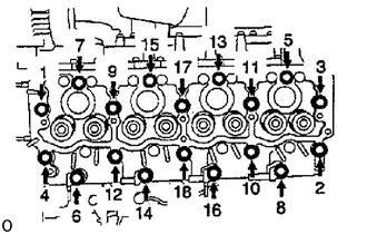
Uniformly loosen and remove the 18 cylinder head bolts, in several passes, in the sequence shown.
- NOTICE:
-
Head warpage or cracking could. result from removing bolts in incorrect order.
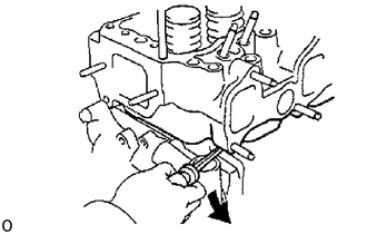
Lift the cylinder head from the dowels on the cylinder block, and place the cylinder head on wooden blocks on a bench.
- HINT:
-
If the cylinder head is difficult to lift off, pry with a screwdriver between the cylinder head and block.
- NOTICE:
-
Be careful not to damage the contact surfaces of the cylinder head and cylinder block.