14B ENGINE MECHANICAL CYLINDER BLOCK CYLINDER BLOCK DISASSEMBLY
PROCEDURE

 11381
1.REMOVE REAR OIL SEAL RETAINER
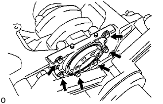
Remove the 6 bolts, oil seal retainer and gasket.
2.CHECK CONNECTING ROD THRUST CLEARANCE
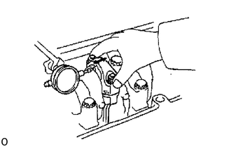
Using a dial indicator, measure the thrust clearance while moving the connecting rod back and forth.
- Standard thrust clearance:
0.200 - 0.320 mm (0.0079 - 0.0126 in.)
- Maximum thrust clearance:
0.40 mm (0.0157 in.)
If the thrust clearance is greater than maximum, replace the connecting rod assembly. If necessary, replace the crankshaft.
3.REMOVE CONNECTING ROD CAPS AND CHECK OIL CLEARANCE
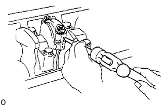
Using a punch or numbering stamp, place matchmarks on the connecting rod and cap to ensure correct reassembly.
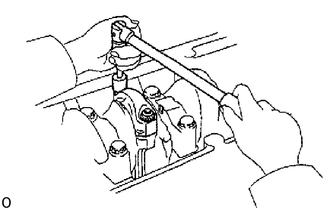
Remove the 2 connecting rod cap nuts.
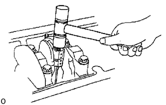
Using a plastic-faced hammer, lightly tap the connecting rod bolts and lift off the connecting rod cap.
- HINT:
-
Keep the lower bearing inserted with the connectingrod cap.
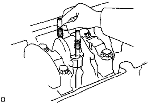
Cover the connecting rod bolts with a short piece of hose to protect the crankshaft from damage.
Clean the crank pin and bearing.
Check the crank pin and bearing for pitting and scratches.
If the crank pin or bearing is damaged. replace the bearings. If necessary, grind or replace the crankshaft.
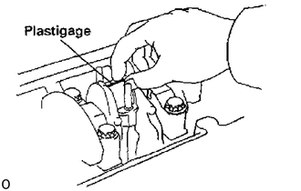
Lay a strip of Plastigage across the crank pin.
Install the connecting rod cap with the 2 nuts.
Click hereEngine / Hybrid System>14B (ENGINE MECHANICAL)>CYLINDER BLOCK>CYLINDER BLOCK ASSEMBLY
- Torque:
- 1st:
68.6 N*m (700 kgf*cm, 51 ft.*lbf)
- 2nd:
Turn 90°
- NOTICE:
-
Do not turn the crankshaft.
Remove the 2 nuts, connecting rod cap and lower bearing. (See procedure (b) and (c) above)
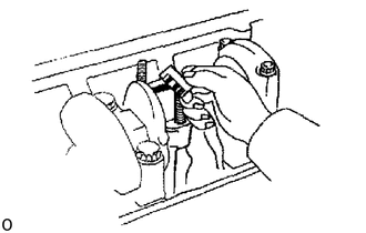
Measure the Plastigage at its widest point.
- Standard oil clearance:
- STD:
0.030 - 0.070 mm (0.0012 - 0.0028 in.)
- U/S 0.25, 0.50, 1.00:
0.030 - 0.072 mm (0.0012 - 0.0028 in.)
- Maximum oil clearance:
0.10 mm (0.0039 in.)
If the oil clearance is greater than maximum, replace the bearings. If necessary, grind or replace the crankshaft.
- HINT:
-
There are 2 sizes of standard bearings, colored yellow and green. If using a standard bearing, select one having the color corresponding to the number on the bearing cap:
1 with Yellow
2 with Green
- Reference:
Standard sized bearing center wall thickness: Yellow 1.480 - 1.485 mm (0.0583 - 0.0585 in.) Green 1.486 - 1.490 mm (0.0586 - 0.0587 in.)
Completely remove the Plastigage.
4.REMOVE PISTON AND CONNECTING ROD ASSEMBLIES
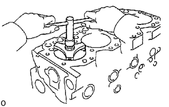
Using a ridge reamer, remove all the carbon from the top of the cylinder.
Push the piston, connecting rod assembly and upper bearing through the top of the cylinder block.
- HINT:
- ·
Keep the bearings, connecting rod and cap together.
·Arrange the piston and connecting rod assemblies in correct order.
5.CHECK CRANKSHAFT THRUST CLEARANCE
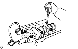
Using a dial indicator. measure the thrust clearance while prying the crankshaft back and forth with a screwdriver.
- Standard thrust clearance:
0.040 - 0.250 mm (0.0016 - 0.0098 in.)
- Maximum thrust clearance:
0.30 mm (0.0118 in.)
If the thrust clearance is greater than maximum, replace the thrust washers as a set.
- Thrust washer thickness:
- STD:
2.430 - 2.480 mm (0.0957 - 0.0976 in.)
- O/S 0.125:
2.493 - 2.543 mm (0.0981 - 0.1001 in.)
- O/S 0.250:
2.555 - 2.605 mm (0.1006 - 0.1026 in.)
6.REMOVE MAIN BEARING CAPS AND CHECK OIL CLEARANCE
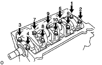
Remove the 10 main bearing cap bolts.
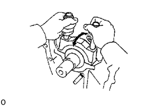
Using the removed main bearing cap bolts, pry the cap back and forth, and remove the main bearing caps, lower thrust washers (No.3 main bearing cap only).[*1]
Lift out the crankshaft.[*2]
- HINT:
- ·
Keep the upper bearings inserted with the cylinder block.
·Arrange the thrust washers in correct order.
Clean each main journal and bearing.
Check each main journal and bearing for pitting and scratches.
If the journal or bearing is damaged, replace the bearings. If necessary. grind or replace the crankshaft.
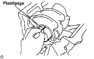
Place the crankshaft on the cylinder block.
Lay a strip of Plastigage across each journal.
Install the 5 main bearing caps with the 10 bolts.
Click hereEngine / Hybrid System>14B (ENGINE MECHANICAL)>CYLINDER BLOCK>CYLINDER BLOCK ASSEMBLY
- Torque:
200 N*m (2,039 kgf*cm, 148 ft.*lbf)
- NOTICE:
-
Do not turn the crankshaft.
Remove the 10 bolts and 5 main bearing caps. (See procedure [*1] and [*2] above)
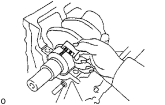
Measure the Plastigage at its widest point.
- Standard oil clearance:
No.3 journal
- STD:
0.060 - 0.104 mm (0.0024 - 0.0041 in.)
- U/S 0.25, 0.50, 1.00:
0.060 - 0.106 mm (0.0026 - 0.0042 in.)
Others
- STD:
0.030 - 0.074 mm (0.0012 - 0.0029 in.)
- U/S 0.25, 0.50, 1.00:
0.030 - 0.076 mm (0.0012 - 0.0030 in.)
- Maximum clearance:
- No.3 journal:
0.15 mm (0.0059 in.)
- Others:
0.10 mm (0.0039 in.)
If the oil clearance is greater than maximum, replace the bearings. If necessary, grind or replace the crankshaft.
- HINT:
-
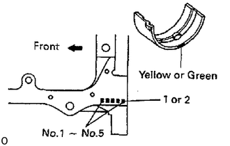
-
There are 2 sizes of standard bearings. colored yellow and green. If using a standard bearing. select one having the color corresponding to the number on the cylinder block:
1 with Yellow
2 with Green
- Reference:
Standard sized bearing center wall thickness: Yellow 2.480 - 2.485 mm (0.0976 - 0.0978 in.) Green 2.486 - 2.490 mm (0.0979 - 0.0980 in.)
Completely remove the Plastigage.
13411
7.REMOVE CRANKSHAFT
Lift out the crankshaft.
Remove the upper bearings and thrust washers from the cylinder block.
- HINT:
-
Arrange the main bearing caps. bearings and thrust washers in correct order.
8.REMOVE CHECK VALVES AND OIL NOZZLES (15B-F, 15B-FT)
9.REMOVE VALVE LIFTERS
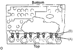
Remove the 8 bolts (B).
- NOTICE:
-
With the engine in the upside down position, the lifters will drop in the engine if the bolts (A) are removed.
Remove the 8 bolts (A), if necessary.
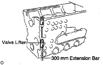
Pull out valve lifters.
- HINT:
-
Arrange the valve lifters in correct order.