14B ENGINE MECHANICAL CYLINDER BLOCK PISTON AND CONNECTING ROD INSPECTION
PROCEDURE

 13101
1.CLEAN PISTON
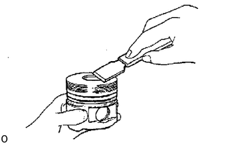
Using a gasket scraper, remove the carbon from the piston top.
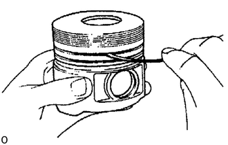
Using a groove cleaning tool or broken ring, clean the piston ring grooves.
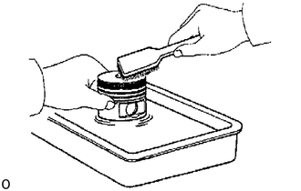
Using solvent and a brush, thoroughly clean the piston.
- NOTICE:
-
Do not use a wire brush.
2.INSPECT PISTON AND PISTON RING
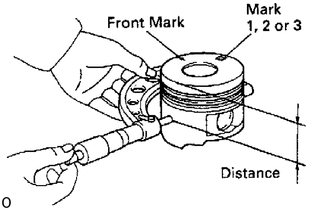
Inspect piston diameter and oil clearance
- HINT:
-
There are 3 sizes of the standard piston diameter, marked "1 ", "2" and "3" accordingly. The mark is stamped on the piston top.
Using a micrometer, measure the piston diameter at right angles to the piston pin center line, the indicated distance from the piston head.
- Distance:
3B 45.20 mm (1.7795 in.) 14B 42.83 mm (1.6862 in.) 15B-F, 15B-FT 50.55 mm (1.9902 in.)
- Piston diameter:
3B STD Mark "1" 101.800 - 101.810 mm (4.0079 - 4.0083 in.) Mark "2" 101.810 - 101.820 mm (4.0083 - 4.0087 in.) Mark "3" 101.820 - 101.830 mm (4.0087 - 4.0090 in.) O/S 0.50 102.300 - 102.330 mm (4.0276 - 4.0287 in.) O/S 0.75 102.550 - 102.580 mm (4.0372 - 4.0386 in.) O/S 1.00 102.800 - 102.830 mm (4.0473 - 4.0484 in.)
14B STD Mark "1" 101.760 - 101.770 mm (4.0063 - 4.0067 in.) Mark "2" 101.770 - 101.780 mm (4.0067 - 4.0071 in.) Mark "3" 101.780 - 101.790 mm (4.0071 - 4.0075 in.) O/S 0.50 102.260 - 102.290 mm (4.0260 - 4.0272 in.) O/S 0.75 102.510 - 102.540 mm (4.0358 - 4.0370 in.) O/S 1.00 102.760 - 102.790 mm (4.0457 - 4.0468 in.)
15B-F STD Mark "1" 107.830 - 107.840 mm (4.2453 - 4.2457 in.) Mark "2" 107.840 - 107.850 mm (4,2457 - 4.2461 in.) Mark "3" 107.850 - 107.860 mm (4.2461 - 4.2465 in.) O/S 0.50 108.330 - 108.360 mm (4.2650 - 4.2661 in.) O/S 0.75 108.580 - 108.610 mm (4.2748 - 4.2760 in.) O/S 1.00 108.830 - 108.860 mm (4.2846 - 4.2858 in.)
15B-FT STD Mark "1" 107.820 - 107.830 mm (4.2449 - 4.2453 in.) Mark "2" 107.830 - 107.840 mm (4.2453 - 4.2457 in.) Mark "3" 107.840 - 107.850 mm (4.2457 - 4.2461 in.) O/S 0.50 108.320 - 108.350 mm (4.2646 - 4.2657 in.) O/S 0.75 108.570 - 108.600 mm (4.2744 - 4.2756 in.) O/S 1.00 108.820 - 108.850 mm (4.2843 - 4.2854 in.)
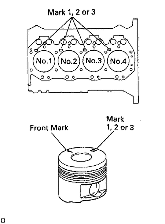
Measure the cylinder bore diameter in the thrust directions.
Click hereEngine / Hybrid System>14B (ENGINE MECHANICAL)>CYLINDER BLOCK>CYLINDER BLOCK INSPECTION
Subtract the piston diameter measurement from the cylinder bore diameter measurement.
- Standard oil clearance:
3B 0.190 - 0.210 mm (0.0057 - 0.0065 in.) 14B 0.230 - 0.250 mm (0.0091 - 0.0098 in.) 15B-F 0.160 - 0.180 mm (0.0063 - 0.0071 in.) 15B-FT 0.170 - 0.190 mm (0.0067 - 0.0075 in.)
- Maximum oil clearance:
3B 0.26 mm (0.0102 in.) 14B 0.30 mm (0.0118 in.) 15B-F 0.23 mm (0.0091 in.) 15B-FT 0.24 mm (0.0084 in.)
If the oil clearance is greater than maximum, replace all the 4 pistons and rebore all the 4 cylinders. If necessary, replace the cylinder block.
- HINT:
-
(Use new cylinder block): Use a piston with the same number mark as the cylinder bore diametermarked on the cylinder block.
Inspect piston ring groove clearance
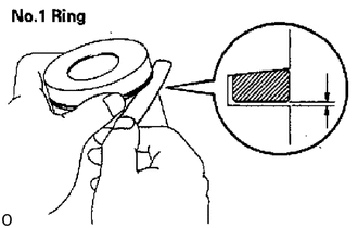
No.1 Ring:
Install a new piston ring to the piston. Using a feeler gauge, measure the clearance between the piston ring and the wall of the ring groove.
- Standard groove clearance:
3B 0.061 - 0.091 mm (0.0024 - 0.0036 in.) 14B 0.062 - 0.092 mm (0.0024 - 0.0036 in.) 15B-F 0.067 - 0.108 mm (0.0026 - 0.0043 in.) 15B-FT 0.065 - 0.107 mm (0.0028 - 0.0042 in.)
- Maximum groove clearance:
0.20 mm (0.0079 in.)
If the clearance is greater than maximum, replace the piston.
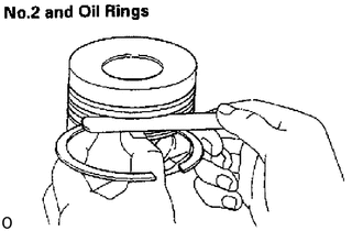
No.2 and Oil Rings:
Using a feeler gauge, measure the clearance between a new piston ring and the wall of the ring groove.
- Standard groove clearance:
- No.2:
0.060 - 0.100 mm (0.0024 - 0.0039 in.)
- Oil:
0.030 - 0.070 mm (0.0012 - 0.0028 in.)
- Maximum groove clearance:
0.20 mm (0.0079 in.)
If the clearance is greater than maximum, replace the piston.
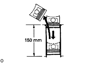
Inspect piston ring end gap
Insert the piston ring into the cylinder bore.
Using a piston. push the piston ring a little beyond the bottom of the ring travel. 150 mm (5.91 in.) from the top of the cylinder block.
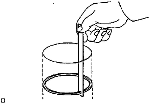
Using a feeler gauge, measure the end gap.
- Standard and gap:
3B No.1 0.350 - 0.620 mm (0.0138 - 0.0244 in.) No.2 0.450 - 0.720 mm (0.0177 - 0.0283 in.) Oil 0.200 - 0.520 mm (0.0079 - 0.0205 in.)
14B No.1 0.350 - 0.620 mm (0.0138 - 0.0244 in.) No.2 0.400 - 0.650 mm (0.0157 - 0.0256 in.) Oil 0.200 - 0.520 mm (0.0079 - 0.0205 in.)
15B-F, 15B-FT No.1 0.350 - 0.570 mm (0.0139 - 0.0224 in.) No.2 0.470 - 0.720 mm (0.0185 - 0.0236 in.) Oil 0.200 - 0.620 mm (0.0079 - 0.0205 in.)
- Maximum and gap:
3B, 14B No.1 1.46 mm (0.0575 in.) No.2 1.61 mm (0.0634 in.) Oil 1.61 mm (0.0634 in.)
15B-F, 15B-FT No.1 1.14 mm (0.0555 in.) No.2 1.61 mm (0.0634 in.) Oil 1.61 mm (0.0634 in.)
If the end gap is greater than maximum, replace the piston ring. If the end gap is greater than maximum, even with a new piston ring, rebore all the 4 cylindersor replace the cylinder block.
3.INSPECT PISTON PIN FIT
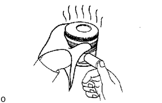
At 60°C (140°F), you should be able to push the piston pin into the piston pin hole with your thumb.
If the pin can be installed at a lower temperature, replace the piston and pin as set.
13201
4.INSPECT CONNECTING ROD
Inspect connecting rod alignment
Using a rod aligner and feeler gauge, check the connecting rod alignment.
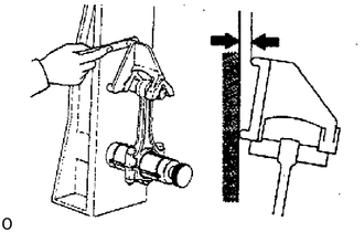
Check for out-of-alignment.
- Maximum out-of-alignment:
0.05 mm (0.0020 in.) per 100 mm (3.94 in.)
If out-of-alignment is greater than maximum. replace the connecting rod assembly.
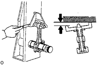
Check for twist
- Maximum twist:
0.15 mm (0.0059 in.) par 100 mm (3.94 in.)
If twist is greater than maximum. replace the connecting rod assembly.
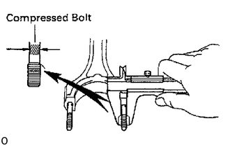
Inspect connecting rod bolts
Using vernier calipers, measure the tension portion diameter.
- Standard diamete:
9.900 - 10.100 mm (0.3898 - 0.3976 in.)
- Minimum diameter:
9.70 mm (0.3819 in.)
If the diameter is less than minimum, replace the connecting rod bolt.
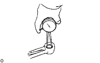
Inspect piston pin oil clearance
Using a caliper gauge, measure the inside diameter of the connecting rod bushing.
- Bushing inside diameter:
- 3B, 14B:
31.999 - 32.009 mm (1.2598 - 1.2602 in.)
- 15B-F, 15B-FT:
33.999 - 34.009 mm (1.3385 - 1.3389 in.)
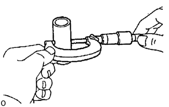
Using a micrometer, measure the piston pin diameter.
- Piston pin diameter:
- 3B, 14B:
32.000 - 32.010 mm (1.2598 - 1.2602 in.)
- 15B-F, 15B-FT:
34.000 - 34.010 mm (1.3386 - 1.3390 in.)
Subtract the piston pin diameter measurement from the bushing inside diameter measurement.
- Standard oil clearance:
- 3B, 14B:
0.004 - 0.014 mm (0.0002 - 0.0006 in.)
- 15B-F, 15B-FT:
0.005 - 0.015 mm (0.0002 - 0.0006 in.)
- Maximum oil clearance:
0.05 mm (0.0020 in.)
If the oil clearance is greater than maximum, replace the bushing. If necessary, replace the piston and piston pin as a set.
If necessary, replace connecting rod bushing
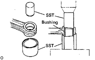
Using SST and a press. press out the bushing.
3B, 14B:
- SST
- 09222-58021 (09222-04016, 09222-04026)
15B-F, 15B-FT:
- SST
- 09222-58012 (09222-01022, 09222-01041)
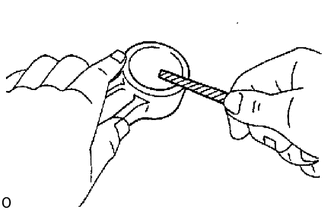
Using a round file, lightly file off any roughness from the small end of the connecting rod.
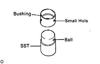
Attach the bushing to SST with the ball of SST inside the oil hole of the bushing.
3B, 14B:
- SST
- 09222-58021 (09222-04021)
15B-F, 15B-FT:
- SST
- 09222-58012 (09222-01031)
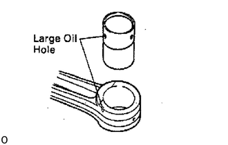
Align the oil holes of a new bushing and the connecting rod.
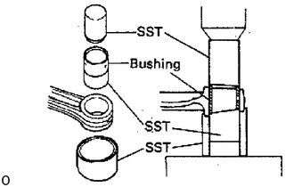
Using SST and a press, press in the bushing.
3B, 14B:
- SST
- 09222-58021 (09222-04016, 09222-04021, 09222-04026)
15B-F, 15B-FT:
- SST
- 09222-58012 (09222-01022, 09222-01031, 09222-01041)
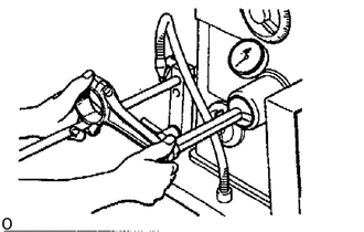
Using a pin hole grinder, hone the bushing to obtain the standard specified clearance (see item (c) above) between the bushing and piston pin.
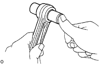
Check the piston pin fit at normal room temperature. Coat the piston pin with engine oil. and push it into the connecting rod with your thumb.